Transcription of 6. How to Use Load Cells - A&D Company
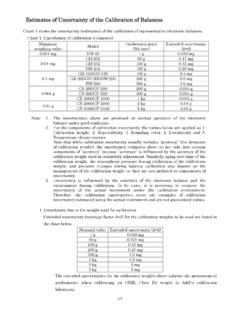
1 6. How to Use load Cells load Cells should be selected after considering the following points. 1. Loading Conditions Determine the loading conditions of the load cell (tension, compression, bending, etc.) that best suit the kind of weighing you would like to perform. 2. Rated Capacity The following points should be considered when selecting a rated capacity. Display of the Required Resolution When the minimum weighing value (1 digit) is small compared to the rated capacity, the load cell output per digit should be above the input sensitivity of the indicator. Example of a value-weighing scale Components Figure pan load cell Indicator Figure 2/6 Force applied onto the weighing pan is converted into electrical signals by the load cell and output to the indicator. Suppose the specifications of the load cell are as follows: Rated capacity: 6 kg Rated output: 1 mV/V Recommended excitation voltage: 10 V When the rated output is 1 mV/V and the excitation voltage is 10 V, the load cell will output 10 mV to the indicator.
2 This is the output voltage when the rated capacity of 6 kg is loaded. ( load ) 6 kg 10 mV (Output Voltage) If we want to weigh an object of 6,000 g using this load cell and display the result from 1 g (1 g is called the minimum weighing value), how many mV will be output for a load of 1 g? Since the load cell will output 10 mV for a load of 6 kg, V mV 6000mV 10 XmV 10 1 X 6000mV 10 : X 6000 : 1 == = = Therefore, the input sensitivity of the indicator must be lower than V. For example, if the input sensitivity of the indicator were V, 1 g display would not be possible. The Strength of the load Cells 1) Platform scales When making a platform scale using a single-point load cell (LC4001 - LC4212), it is acceptable for the weighing capacity of the scale to be equal to the rated capacity of the load cell. For instance, if we want to make a scale with a capacity of 100 kg, we can use a load cell whose rated capacity is 100 kg.
3 However, the initial (tare) load must not exceed the safe tare limit (maximum dead weight) of the load cell. If the initial load is very large, the rated capacity + the safe tare limit is treated as the rated capacity. 2) Industrial hopper scales, etc. The rated capacity of a load cell for purposes other than platform scales can be determined as follows. However, the rated capacity must be sufficiently large if overloading or transverse loading may occur. 3/6 3/6 NffWWfL32211)( + > L : Rated capacity N : Number of load Cells to be used W1 : Net measurement weight W2 : Weight of the hopper itself f1 : Dynamic factor (typically ) f2 : Eccentricity factor (typically ) f3 : Imbalance factor ( when N = 3, and when N = 4) For example, when the net measurement weight is 8 t, the weight of the hopper is 3 t, and the number of load Cells to be used is four, t5 ) ( L = + > it is therefore desirable to use four load Cells that each have a rated capacity of 5 t.
4 Accuracy of Measurement load cell specifications must be checked to ensure that they satisfy the required accuracy of measurement. The factors that influence the accuracy are nonlinearity, hysteresis error, repeatability, and temperature effects on zero balance and span. Recently, it is more common to express nonlinearity, hysteresis error, and repeatability together as the combined error. When the required accuracy is represented as , one of the following formulas applies: (1) If the combined error is specified in the catalog, 2212)(ttWNLSCZ + +> : Measurement accuracy of the load cell (%) C : Combined error (%) Z : Temperature effect on zero balance (%/ C) S : Temperature effect on span (%/ C) L : Rated capacity of the load cell N : Number of load Cells to be used W1 : Maximum load to be measured t : Temperature variation range of the load cell ( C) 4/6 4/6 (2) If nonlinearity, hysteresis error, and repeatability are specified separately in the catalog, 221222)(ttWNLSRHLZ + +++> : Measurement accuracy of the load cell (%) L : Nonlinearity (%) H : Hysteresis error (%) R : Repeatability (%) Z.
5 Temperature effect on zero balance (%/ C) S : Temperature effect on span (%/ C) L : Rated capacity of the load cell N : Number of load Cells to be used W1 : Maximum load to be measured t : Temperature variation range of the load cell ( C) The elements that will not be of practical concern should be deleted from these formulas. For instance, pressing the zero button will prevent a temperature change from causing a zero balance error. In such a case, 2)(tZ can be deleted from the formula. There may also be applications in which we want to increase the resolution but don t need to worry about temperature changes. Therefore, we can make flexible decisions based on usage. 5/6 5/6 Let s look at an actual example with a 10 kg scale using an LC4102-K010. Suppose the temperature range will be 20 10 C.
6 The above specifications show the temperature effects on zero balance and span per 10 C, so these values have to be changed to those per 1 C. The temperature variation range is 20 (from +10 C to -10 C ). However, if the zero key is pressed for every measurement, the temperature effect on zero balance can be ignored. Let s now put these numbers into the formula. C : Combined error (%) Z : Temperature effect on zero balance (%/ C) (The catalog specification value ( ) is for a change of 10 C. This value is recalculated here for a 1 C change.) S : Temperature effect on span (%/ C) (Recalculated as above) L : Rated capacity of the load cell 10 kg N : Number of load Cells to be used 1 W1 : Maximum load to be measured 10 kg t : Temperature variation range of the load cell ( C) 1 (the temperature effect on zero balance because the zero key will be pressed) / 20 (the temperature effect on span) Specifications Rated capacity 1 mV/V+15%-0% Safe overload 300% of Max.
7 Safe overload 400% of Combined error of Recommended excitation voltage DC 12 V Maximum excitation voltage DC 15 V Zero balance 20 5% of Input terminal resistance Approx. 400 Output terminal resistance 350 5 Insulation resistance 500 M /DC 50 V Compensated temperature range -10 to 40 C Temperature effect on zero balance of C Temperature effect on span of load /10 C thickness / length 4 / m Platform size 400 400 mm Dust and water proof IP54 6/6 6/6 % ) ( + +> Therefore, the scale will be sufficiently accurate if the resolution is 1/3000. Environment For environmental conditions such as water vapor and corrosive gas, a corrosion-resistant load cell has to be used. In general, hermetically-sealed load Cells , especially those made of stainless steel, have high corrosion and environmental resistance. If we want to use a load cell in a potentially explosive atmosphere, we must choose a load cell certified as intrinsically safe or flameproof.
8 3. Precautions for Use 1. Cables for electric current normally have conductor resistance. Consequently, the current magnitude that is passed through the cable will vary as the temperature varies. Likewise, the conductor resistance of a load cell cable varies with temperature, whose effect is not negligible when the cable is long. In such cases, the sensing circuit of the indicator is used to correct it. 2. When there is a high-voltage power supply near a load cell and its cables, keep a distance of more than 300 mm, arrange other piping, and protect the load cell from the inductive interference. Shielded cables should be used for load Cells . 3. Consider using junction boxes between load Cells and indicators for maintenance such as checkups and replacements. 4. Have a single-point ground on the indicator side since the shield of the load cell cable is suspended on the load cell side.
9 If a junction box separates the indicator and load cell, make sure that the cable shielding continues within the box. If the grounding is multiple-point, electrical potential differences occur between the grounds, which makes the noise more likely to occur. 5. A rapid change in the surrounding temperature may cause a temperature difference between the inside and the outside of a load cell and this may change the load cell characteristics temporarily. These changes, referred to as transient temperature characteristics, require appropriate countermeasures. 6. Finish all electrical welding before installing a load cell. If welding is performed after load cell installation, ensure that no electric current is passing through the load cell. 7. For a load cell with a low rated capacity, fix the cables on the stationary side to eliminate the effect of the cord.