Transcription of 6 INTRODUCTION TO COLUMN BUCKLING
1 INTRODUCTION TO COLUMN BUCKLING . 6 INTRODUCTION TO COLUMN BUCKLING . INTRODUCTION AND BASIC CONCEPTS. There are many types of compression members, the COLUMN being the best known. Top chords of trusses, bracing members and compression flanges of built up beams and rolled beams are all examples of compression elements. Columns are usually thought of as straight vertical members whose lengths are considerably greater than their cross- sectional dimensions. An initially straight strut or COLUMN , compressed by gradually increasing equal and opposite axial forces at the ends is considered first. Columns and struts are termed long or short depending on their proneness to BUCKLING .
2 If the strut is short , the applied forces will cause a compressive strain, which results in the shortening of the strut in the direction of the applied forces. Under incremental loading, this shortening continues until the COLUMN "squashes". However, if the strut is long , similar axial shortening is observed only at the initial stages of incremental loading. Thereafter, as the applied forces are increased in magnitude, the strut becomes unstable . and develops a deformation in a direction normal to the loading axis. (See ). The strut is in a buckled state. BUCKLING behaviour is thus characterized by deformations developed in a direction (or plane) normal to that of the loading that produces it.
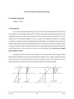
3 When the applied loading is increased, the BUCKLING deformation also increases. BUCKLING occurs mainly in members subjected to compressive forces. If the member has high bending stiffness, its BUCKLING resistance is high. Also, when the member length is increased, the BUCKLING resistance is decreased. Thus the BUCKLING resistance is high when the member is stocky ( the member has a high bending stiffness and is short) conversely, the BUCKLING resistance is low when the member is slender . Structural steel has high yield strength and ultimate strength compared with other construction materials. Hence compression members made of steel tend to be slender.
4 BUCKLING is of particular interest while employing steel members, which tend to be slender, compared with reinforced concrete or prestressed concrete compression members. Members fabricated from steel plating or sheeting and subjected to compressive stresses also experience local BUCKLING of the plate elements. This chapter introduces BUCKLING in the context of axially compressed struts and identifies the factors governing the BUCKLING behaviour. The local BUCKLING of thin flanges/webs is not considered at this stage. These concepts are developed further in a subsequent chapter . Copyright reserved Version II 6-1. INTRODUCTION TO COLUMN BUCKLING .
5 A short COLUMN fails by compression yield Buckled shape . Fig 1: short vs long columns A long COLUMN fails by predominant BUCKLING Version II 6-2. INTRODUCTION TO COLUMN BUCKLING . ELASTIC BUCKLING OF AN IDEAL COLUMN OR STRUT WITH PINNED. END. To begin with, we will consider the elastic behaviour of an idealized, pin-ended, uniform strut. The classical Euler analysis of this problem makes the following assumptions. the material of which the strut is made is homogeneous and linearly elastic ( it obeys Hooke's Law). the strut is perfectly straight and there are no imperfections. the loading is applied at the centroid of the cross section at the ends.
6 Pcr . y x B. Pcr Fig. 2 COLUMN BUCKLING We will assume that the member is able to bend about one of the principal axes. (See Fig. 2). Initially, the strut will remain straight for all values of P, but at a particular value P = Pcr, it buckles. Let the BUCKLING deformation at a section distant x from the end B be y. The bending moment at this section = The differential equation governing the small BUCKLING deformation is given by d2y EI = Pcr . y dx 2. The general solution for this differential equation is Pcr P. y = A1 cos x + B1 sin x cr EI EI. where A1 and A2 are constants. Since y = 0 when x = 0, A1 = 0. Version II 6-3. INTRODUCTION TO COLUMN BUCKLING .
7 When x = , y = 0;. Pcr Hence B1 sin =0. EI. Pcr Either B1 = 0 or sin =0. EI. B1 = 0 means y = 0 for all values of x ( the COLUMN remains straight). P. Alternatively sin cr = 0. EI. This equation is satisfied only when Pcr = 0 , , 2 ,.. EI. 2 EI 4 2 EI n 2 2 EI. Pcr = , .. 2 2 2. where n is any integer. 9 2 EI. 9. 2. P. EI . 2. 2 EI. Unstable BUCKLING modes All values above 2 . 2. are unstable 4 EI 2. 4. 2. 1 2 EI. 2.. Fig. 3 BUCKLING load Vs Lateral deflection Relationship While there are several BUCKLING modes corresponding to n = 1, 2, 3, , the lowest stable BUCKLING mode corresponds to n = 1. (See Fig. 3). Version II 6-4. INTRODUCTION TO COLUMN BUCKLING .
8 The lowest value of the critical load ( the load causing BUCKLING ) is given by 2 EI. Pcr = (1). 2. Thus the Euler BUCKLING analysis for a " straight" strut, will lead to the following conclusions: 1. The strut can remain straight for all values of P. 2 EI. 2. Under incremental loading, when P reaches a value of Pcr =. 2. the strut can buckle in the shape of a half-sine wave; the amplitude of this BUCKLING deflection is indeterminate. 3. At higher values of the loads given by n EI other sinusoidal buckled 2 2. 2. shapes (n half waves) are possible. However, it is possible to show that the COLUMN will be in unstable equilibrium for all values of P >.
9 2 EI. 2. whether it be straight or buckled. This means that the slightest disturbance will cause the COLUMN to deflect away from its original position. Elastic Instability may be defined in general terms as a condition in which the structure has no tendency to return to its initial position when slightly disturbed, even when the material is assumed to have an infinitely large yield stress. Thus 2 EI. Pcr = ( 2). 2. represents the maximum load that the strut can usefully support. It is often convenient to study the onset of elastic BUCKLING in terms of the mean applied compressive stress (rather than the force). The mean compressive stress at BUCKLING , cr , is given by Pcr 2 EI.
10 Cr = =. A A 2. where A = area of cross section of the strut. If r = radius of gyration of the cross section, then I = Ar2, 2E r2 2E 2E. Hence, cr = = = 2 (3). 2 ( / r ) 2 . Version II 6-5. INTRODUCTION TO COLUMN BUCKLING . where = the slenderness ratio of the COLUMN defined by = / r The equation cr = ( 2E)/ 2, implies that the critical stress of a COLUMN is inversely proportional to the square of the slenderness ratio of the COLUMN (see Fig. 4). cr Elastic BUCKLING stress (Mpa) ( cr) defined by ( 2E/ 2). = /r Fig. 4 Euler BUCKLING relation between cr and . STRENGTH CURVE FOR AN IDEAL STRUT. We will assume that the stress-strain relationship of the material of the COLUMN is defined by Fig.