Transcription of 7.9 Design Guidelines – Rock Riprap 7.9.1 Rock Riprap
1 Channels 2000 ConnDOT Drainage Design Guidelines Rock RiprapThis section contains Design Guidelines for the Design of rock Riprap . Guidelines are providedfor bank slope, rock size, rock gradation, Riprap layer thickness, filter Design , edge treatment andconstruction considerations. In addition, typical construction details are illustrated. In most cases,the Guidelines presented apply equally to rock and rubble Riprap .
2 Guidelines for other types arepresented in SlopeA primary consideration in the Design of stable Riprap bank protection schemes is the slope ofthe channel bank. For Riprap installations, normally the maximum recommended face slope is1 SizeThe stability of a particular Riprap particle is a function of its size, expressed either in terms of itsweight or equivalent diameter. In the following sections, relationships are presented for evaluatingthe Riprap size required to resist particle and wave erosion ErosionTwo methods or approaches have been used historically to evaluate a material's resistance toparticle erosion.
3 These methods are the permissible velocity approach and the permissible tractiveforce (shear stress) approach. Under the permissible velocity approach the channel is assumedstable if the computed mean velocity is lower than the maximum permissible velocity. The tractiveforce (boundary shear stress) approach focuses on stresses developed at the interface betweenflowing water and materials forming the channel ChannelsConnDOT Drainage ManualMay RelationshipA Riprap Design relationship that is based on tractive force theory yet has velocity as its primarydesign parameter is presented in Equation The Design relationship in Equation is basedon the assumption of
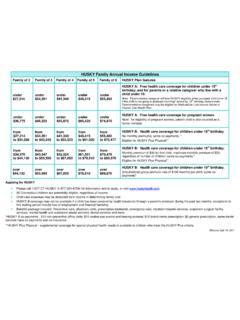
4 Uniform, gradually varying flow. Figure presents a graphical solutionto Equation Equation can be solved using Figures 7-26 and = 94 Va3 / ( )( D50 = Va3 / ( ) )( )Where: D50= the median Riprap particle size, m (ft)C= correction factor (described below)Va= the average velocity in the main channel, m/s (ft/s)davg= the average flow depth in the main flow channel, m (ft)K1is defined as:K1 = [1-(sin2 /sin2 )] ( )Where: =the bank angle with the horizontal =the Riprap material's angle of reposeThe average flow depth and velocity used in Equation are main channel values.
5 The mainchannel is defined as the area between the channel banks (see Figure 7-24 below).Figure 7-24 Definition Sketch; Channel Flow DistributionChannels 2000 ConnDOT Drainage ManualEquation is based on a rock Riprap specific gravity of , and a stability factor of and present correction factors for other specific gravities and stability = (Ss - 1) ( )Where: Ss = the specific gravity of the rock riprapCsf = ( ) ( )Where.
6 SF = the stability factor to be correction factors computed using Equations and are multiplied together to form asingle correction factor C. This correction factor, C, is then multiplied by the Riprap size computedfrom Equation to arrive at a stable Riprap size. Figure 7-28 provides a solution to and using correction factor stability factor, SF, used in Equations and requires additional explanation. Thestability factor is defined as the ratio of the average tractive force exerted by the flow field and theriprap material's critical shear stress.
7 As long as the stability factor is greater than 1, the criticalshear stress of the material is greater than the flow induced tractive stress, the Riprap is considered tobe stable. As mentioned above, a stability factor of was used in the development of stability factor is used to reflect the level of uncertainty in the hydraulic conditions at aparticular site. Equation is based on the assumption of uniform or gradually varying flow. Inmany instances, this assumption is violated or other uncertainties come to bear.
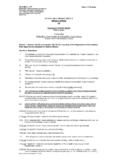
8 For example, debrisand/or ice impacts, or the cumulative effect of high shear stresses and forces from wind and/or boatgenerated waves. The stability factor is used to increase the Design rock size when these conditionsmust be considered. Table 7-7 presents Guidelines for the selection of an appropriate value for thestability ChannelsConnDOT Drainage ManualOctober 2000 Figure 7-25 Riprap Size Relationship (metric units)
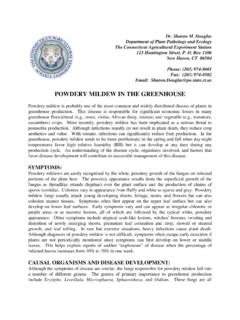
9 Channels 2000 ConnDOT Drainage ManualFigure Riprap Size Relationship (English units) ChannelsConnDOT Drainage ManualDecember 2003 Figure 7-26 Bank Angle Correction Factor (K1) Nomograph =Bank angle with horizontal = Material angle of reposeSee Figure 7-27 or Slope (o) (o)ExampleGiven:Find:Solution.
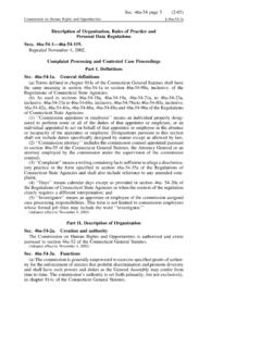
10 = 18oK1 = 42oVery angularK1 = = 457 mm ( ft)15 Channels 2000 ConnDOT Drainage ManualFigure 7-27 Angle Of Repose Of Riprap In Terms Of Mean Size And Shape Of Stone(metric units)Angle of Repose (degrees) ChannelsConnDOT Drainage ManualOctober 2000 Figure Angle Of Repose Of Riprap in Terms Of Mean Size and Shape Of Stone(English units)ANGLE OFREPOSE ( )