Transcription of 7 Fluidisation - particles.org.uk
1 7 fluidisation The Fluidisation principle is straightforward: passing a fluid upwards through a packed bed of solids produces a pressure drop due to fluid drag. When the fluid drag force is equal to the bed weight the particles no longer rest on each other; this is the point of Fluidisation . The superficial velocity at this point is known as the minimum fluidising velocity (Umf). If the fluid velocity is increased further the pressure drop does not significantly increase it remains equal to the bed weight per unit area, but the bed may expand; grow taller as illustrated in Figure Commercial gaseous fluidised beds are usually operated at flow rates many times that required for minimum Fluidisation , typically 5 to 20 times. Liquid fluidised beds operate at values closer to Umf. A material balance indicates that, in general iofiHHCC= ( ) On page 53, the hypothetical case was made for turning the vessel containing hindered settling solids upside down and noting that the liquid velocity upwards, required to maintain the position of the interface, is equal to the settling velocity of the solids in an otherwise stationary liquid.
2 This upward fluid flow, and balance of forces, is the hydrodynamic condition that exists during Fluidisation . Thus, the Richardson and Zaki equation, page 54, is also valid for liquid fluidised systems and the minimum fluidising velocity is a superficial velocity, as illustrated in Figure inverted. Fluidisation is a popular means of contacting solids and a fluid because of the high degree of mixing and the resulting high transfer coefficients (heat and mass). There are numerous examples including: catalytic conversion of hydrocarbons, drying, combustion, calcination (application of heat to decompose a solid for example calcium carbonate to oxide or gypsum solids to plaster), agglomeration, etc. Another useful advantage is the uniformity of the bed temperature, so that heat sensitive materials can be treated in a well controlled environment. However, the biggest disadvantage of gas beds is the need for dust control and treatment which can be more expensive than the capital and running cost of the fluidised bed itself.
3 An example of a gaseous fluidised bed is provided in Figure In the figure several important aspects are recorded: the gas fluidised bed is not uniform, but bubbles of gas within the bed are observed (see Section ), a distributor plate supports the solids and distributes the fluidising gas, above the bed the vessel diameter increases thereby reducing the gas velocity so that entrained particles may drop back into the bed from the freeboard and a gas cyclone is used for primary particle separation from the gas stream. The cyclone dip tube enters the bed hence preventing gas from entering the cyclone from the Fig. Bed expansion during particulate Fluidisation mass of solids is the same in all beds Fig. Example design of a gas fluidised bed 68 Fluidisation solid s outlet. The cyclone inlet is simply open to the freeboard. Solids feed into a fluidised bed is often a significant challenge. Screw feeders used on free flowing materials may form a seal to prevent the gas escaping but, this cannot be guaranteed and rotary valves may need to be used.
4 Reaction rates within the fluidised bed are usually rapid, hence the bed material is often inert, or reaction product, the actual amount of solid reacting within the bed may be very small; in fluidised bed combustion of coal a bed of calcium carbonate may be used and the coal particles may only be between to 2% of the bed by mass. The calcium carbonate becomes oxide and then reacts to form calcium sulphate if sulphur dioxide is present. This provides in-situ sulphur dioxide emission removal. A high pressure drop over the distributor plate is usually required to ensure adequate distribution of fluidising gas over the entire area of the bed. Solids off-take can be by a simple overflow or via the gas outlet, or cyclone. Minimum fluidising velocity The fundamental equation for fluid flow through porous media, under laminar flow conditions, is Darcy s law, equation ( ). In most instances the Kozeny-Carman equation ( ) is preferred because it has an explicit expression for permeability in terms of bed porosity and specific surface.
5 The pressure at the base of a fluid (due to fluid weight) comes from the static component of Bernoulli s equation gLP = where L is fluid height, g is the acceleration due to gravity and is the fluid density. For a suspension, a similar equation is valid but, for the static pressure due to the solid particles, we must take account of buoyancy and the proportion of particles present. Clearly, if there are no solids present there would be zero static pressure due to solids but rather than use the solid concentration by volume fraction we use the porosity, see Figure , thus )1()(s = gLP ( ) where s is the true solid density (kg m 3). Combining equations ( ) and ( ) remembering that we stated that Fluidisation occurs when the bed weight (per unit area) equals the fluid drag gives )1()(smf =gkU ( ) the minimum fluidising velocity is a superficial velocity (not interstitial). It is common to see equation ( ) written with the permeability term expanded as provided by the Kozeny-Carman equation, see equation ( ), and assuming spherical particles, equation ( ), gives an alternative equation for minimum fluidising velocity )1(180)(2Sv3smf =xgU ( ) Fig.
6 Up to the Fluidisation point pressure with superficial velocity is linear in accordance with Darcy s law: oLUkP = On increasing the flow particles rearrange before Fluidisation giving rise to the maximum on decreasing flow a lower pressure drop may be found, giving a hysterisis. Fig. Pressure gradient with superficial velocity up to and after Fluidisation linear as above whilst L is constant, but drops when L increases: oUkLP = Fundamentals of Particle Technology 69 Types of Fluidisation On increasing the fluid velocity, up to the point of Fluidisation , flow patterns are usually well described by Darcy s law. However, after the Fluidisation point two very distinct types of fluid flow are observed: particulate and aggregative Fluidisation . In the former case the bed behaves in a uniform manner: as the flow rate is increased the bed height increases; hence, the increasing fluid flow simply goes to expand the bed, as illustrated in Figure The overall pressure drop remains constant, and equal to the bed weight per unit area, until entrained particles are elutriated out by the fluid flow.
7 In particulate Fluidisation the fluid superficial velocity and bed porosity may be related by the Richardson and Zaki expression, see equation ( ). In aggregating, or bubbling, Fluidisation aggregates (of fluid) may be observed within the fluidised bed that move rapidly to the surface. This type of Fluidisation is often associated with the Fluidisation of solids using gases. This is probably the most commercially important type of Fluidisation . Hence, an understanding of aggregative, or bubbling, Fluidisation is important. See the pictures of bubble formation and passage through a bed illustrated in Figure In an aggregative fluidised bed the fluid can pass through the bed in a similar fashion to particulate Fluidisation and bubbles of fluid form. The bubbles may travel very quickly through the bed hence in the case of catalytic cracking of hydrocarbons this provides a way in which some hydrocarbon vapour can by-pass the catalyst and, therefore, reaction.
8 So, a bubbling bed has an emulsion phase surrounding the bubble and a lean phase where the bubble is lean of solids. These bubbles form spontaneously and, because most fluidisations of commercial interest take place in bubbling beds, a large amount of research has gone into characterising and understanding bubble behaviour. There are several correlations designed to help answer the simple question: will a bed bubble or not? The simplest is based on the Froude number: xgUFr2mf= ( ) For high (>1) values bubbling is more likely. Other correlations include the use of Reynolds number, density ratio and bed ratio: mfRe'xU=; s; bmfdL where Lmf is the bed height at minimum Fluidisation and db is the bed diameter. The empirical correlations are: 100Re'Frbmfs< dL particulate Fluidisation 100Re'Frbmfs> dL bubbling Fluidisation Fig. Numerical simulation of aggregative (bubbling) Fluidisation : a gas bubble rising in a fluidised bed.
9 Note the scale bar on the left: white represents 100% voidage and black 50% voidage. The bed is just fluidised in the bottom picture. 70 Fluidisation A more comprehensive attempt to describe fluidising behaviour, than the empirical correlations provided above, has been published and is known as the Geldart Powder Classification Chart (1973, Powder Technology, 7, p285), see Figure The following regions are identified in Geldart s chart: Group A: Aeratable, may not bubble, if it does then bed expands before bubbling, may have fast moving bubbles less than 100 mm. Groups B & D: large bubbles, may form slugs. Group D gives slow bubbles. Group C: Cohesive, high interparticle forces leads to difficult Fluidisation , may form channels or slugs instead. Bed design and bubbling behaviour In practice, many different types of Fluidisation may occur and the vessel geometry can influence this significantly. Figure illustrates other Fluidisation bed behaviour due to: slugging, channelling and spouting.
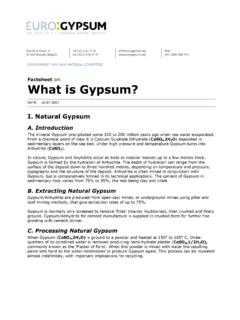
10 In the latter two cases, a special design is sometimes used in which the bed is continually in axial motion, and a distributor plate might not be employed. Also included on Figure is the effect of the bed behaviour on the pressure curve illustrated in Figure In another special case, the calcination of gypsum, a conical fluidised bed is used. The application here is to convert the gypsum (calcium sulphate dihydrate) into plaster (calcium sulphate hemihydrate), for use as plasterboard on walls, fillers, etc. and the particles are gypsum produced from flue gas desulphurisation (FGD) at large power stations. The calcinations can be written: CaSO4. H2O + 1 H2O The particle Sauter mean diameter is 40 m and the density is approximately g cm 3. The powder is well into Geldart s Group A which should provide a reasonable quality Fluidisation , but the FGD process is a wet one and although the particles are dewatered the product still has sufficient residual moisture for the wetting force to be very strong causing particle cohesion.