Transcription of 7 Series FPGAs Memory Interface Solutions
1 7 Series FPGAs Memory Interface SolutionsUser GuideUG586 March 1, 20117 Series FPGAs Memory Interface March 1, 2011 Xilinx is providing this product documentation, hereinafter Information, to you AS IS with no warranty of any kind, express or implied. Xilinx makes no representation that the Information, or any particular implementation thereof, is free from any claims of infringement. You are responsible for obtaining any rights you may require for any implementation based on the Information. All specifications are subject to change without notice. XILINX EXPRESSLY DISCLAIMS ANY WARRANTY WHATSOEVER WITH RESPECT TO THE ADEQUACY OF THE INFORMATION OR ANY IMPLEMENTATION BASED THEREON, INCLUDING BUT NOT LIMITED TO ANY WARRANTIES OR REPRESENTATIONS THAT THIS IMPLEMENTATION IS FREE FROM CLAIMS OF INFRINGEMENT AND ANY IMPLIED WARRANTIES OF MERCHANTABILITY OR FITNESS FOR A PARTICULAR PURPOSE. Except as stated herein, none of the Information may be copied, reproduced, distributed, republished, downloaded, displayed, posted, or transmitted in any form or by any means including, but not limited to, electronic, mechanical, photocopying, recording, or otherwise, without the prior written consent of Xilinx.
2 Copyright 2010 Xilinx, Inc. XILINX, the Xilinx logo, Virtex, Kintex, Artix, Spartan, ISE, and other designated brands included herein are trademarks of Xilinx in the United States and other countries. AMBA is a registered trademark of ARM in the EU and other countries. All other trademarks are the property of their respective HistoryThe following table shows the revision history for this document. DateVersionRevision03/01 Initial Series FPGAs Memory Interface March 1, 2011 Revision History .. 2 Preface: About This GuideGuide Contents .. 5 References .. 5 Additional Resources .. 6 Conventions .. 6 Typographical .. 6 Online Document .. 7 List of Acronyms.. 7 Chapter 1: DDR3 SDRAM Memory Interface SolutionIntroduction .. 9 New Features .. 9 Getting Started with the CORE Generator Software.. 9 System Requirements .. 9 Customizing and Generating the Core .. 10 Creating 7 Series FPGA DDR3 Memory Controller Block design .
3 18 Directory Structure and File Descriptions .. 31 Quick Start Example design .. 36 Modifying the Example design .. 39 Getting Started with EDK .. 48 Core Architecture .. 48 Overview .. 48 user Interface .. 50 AXI4 Slave Interface Block .. 53 Arbitration in AXI Shim .. 56 user Interface Block .. 57 Native Interface .. 57 Clocking Architecture .. 60 Memory Controller .. 63 PHY .. 66 Designing with the Core .. 89 Interfacing to the Core .. 89 AXI4 Slave Interface .. 89 AXI addressing .. 89 user Interface .. 89 Native Interface .. 95 Physical Layer Interface (Non- Memory Controller design ) .. 96 Customizing the Core .. 97 design Guidelines .. 102 DDR3 SDRAM .. 102 Supported Devices for 7 Series FPGAs .. 123 Table of Series FPGAs Memory Interface SolutionsUG586 March 1, 2011 Chapter 2: QDRII+ Memory Interface SolutionIntroduction .. 125 Getting Started with the CORE Generator Software.
4 125 System Requirements .. 125 Customizing and Generating the Core .. 126 Creating the 7 Series FPGA QDRII+ SRAM Memory design .. 134 MIG Directory Structure and File Descriptions .. 142 Core Architecture .. 146 Overview .. 146 user Interface .. 148 Clocking Architecture .. 150 Physical Interface .. 151 Write Path .. 154 Read path .. 156 Calibration .. 157 Customizing the Core .. 160 design Guidelines .. 161 design Rules .. 161 Trace Length Requirements .. 161 Pinout Requirements .. 162I/O Standards .. 1637 Series FPGAs Memory Interface March 1, 2011 PrefaceAbout This GuideXilinx 7 Series FPGAs include three unified FPGA families that are all designed for lowest power to enable a common design to scale across families for optimal power, performance, and cost. The Artix -7 family is optimized for lowest cost and absolute power for the highest volume applications. The Virtex -7 family is optimized for highest system performance and capacity.
5 The Kintex -7 family is an innovative class of FPGAs optimized for the best price-performance. This guide serves as a technical reference to using, customizing, and simulating LogiCORE IP DDR3 SDRAM Memory Interface cores for 7 Series ContentsThis manual contains the following chapters: Chapter 1, DDR3 SDRAM Memory Interface Solution, describes the bank and pin rules for DDR3 SDRAM interfaces in 7 Series FPGAs . Chapter 2, QDRII+ Memory Interface Solution describes the architecture of the 7 Series FPGA QDRII+ Memory Interface core and provides details on customizing and interfacing to the , 7 Series FPGAs SelectIO Resources user AMBA , DDR3 SDRAM Standard, JEDEC Solid State Technology , EDK Concepts, Tools, and , Embedded System Tools Reference , DDR2-533 Memory design Guide For Two-DIMM Unbuffered Systems. Micron Technology, Pro Logic Analyzer , Command Line Tools user Guide, , Synthesis and Simulation design Guide10.
6 DS176, 7 Series FPGAs Memory Interface Solutions Data Sheet11. PlanAhead design Analysis , Xilinx Timing Constraints user Series FPGAs Memory Interface SolutionsUG586 March 1, 2011 Preface:About This , Virtex-5 FPGA ML561 Memory Interfaces Development Board user Guide14. DS182, 7 Series FPGAs Data Sheet: DC and Switching , ChipScope Pro Software and Cores user Guide16. "Improving DDR SDRAM Efficiency with a Reordering Controller" XCELL Journal Issue 69 Additional ResourcesTo find additional documentation, see the Xilinx website at: search the Answer Database of silicon, software, and IP questions and answers, or to create a technical support WebCase, see the Xilinx website at: document uses the conventions listed in this section. An example illustrates each typographical conventions are used in this document:ConventionMeaning or UseExampleCourier fontMessages, prompts, and program files that the system displaysspeed grade: - 100 Courier boldLiteral commands that you enter in a syntactical statementngdbuild design_nameHelvetica boldCommands that you select from a menu File OpenKeyboard shortcutsCtrl+CItalic fontVariables in a syntax statement for which you must supply valuesngdbuild design_nameReferences to other manualsSee the Command Line Tools user Guide for more in textIf a wire is drawn so that it overlaps the pin of a symbol, the two nets are not brackets [ ]An optional entry or parameter.
7 However, in bus specifications, such as bus[7:0], they are [option_name] design_nameBraces { }A list of items from which you must choose one or morelowpwr ={on|off}7 Series FPGAs Memory Interface March 1, 2011 List of AcronymsOnline DocumentThese conventions are used in this document:List of AcronymsThe following acronyms are used in this document:Vertical bar |Separates items in a list of choiceslowpwr ={on|off}Vertical material that has been omittedIOB #1: Name = QOUT IOB #2: Name = CLKIN ..Horizontal ellipsis ..Repetitive material that has been omittedallow block block_name loc1 loc2 .. locn;ConventionMeaning or UseExampleConventionMeaning or UseExampleBlue textCross-reference link to a location in the current documentSee the section Additional Resources for Title Formats in Chapter 1 for , underlined textHyperlink to a website (URL)Go to for the latest speed Extensible InterfaceBSBBase System BuilderCIOC ommon I/ODCBData Circular BufferDCID igitally Controlled ImpedanceDDRD ouble Data RateDLLD elay Locked LoopECCE rror Correction CodeEDKE mbedded Development KitFPGAF ield Programmable Gate ArrayFPSFine Phase ShiftIBISI/O Buffer Information SpecificationICONI ntegrated Series FPGAs Memory Interface SolutionsUG586 March 1, 2011 Preface.
8 About This GuideILAI ntegrated Logic AnalyzerIOBI nput/Output BlockLFSRL inear Feedback Shift RegisterLUTLook-Up TableMCMemory ControllerMIGM emory Interface GeneratorMMCMM ixed-Mode Clock ManagerMRCCM ulti-Region Clock CapableMRSMode Register SetNOPNo OperationODTOn-Die TerminationOTFOn the FlyPHYP hysical LayerPRBSP seudo Random Binary SequenceQDRQuad Data RateRLDRAMR educed-Latency Dynamic Random Access MemorySDRS ingle Data RateSDRAMS ynchronous Dynamic Random Access MemorySPDS erial Presence DetectSRAMS tatic Random Access MemorySRCCS ingle-Region Clock CapableSSOS imultaneous Switching OutputTDMTime Division MultiplexingTIGT iming IgnoreUCFUser Constraints FileUIUser InterfaceVCOV oltage Controlled OscillatorVIOV irtual I/OXPSX ilinx Platform StudioAcronymDefinition7 Series FPGAs Memory Interface March 1, 2011 Chapter 1 DDR3 SDRAM Memory Interface SolutionIntroductionThe 7 Series FPGAs Memory Interface Solutions core is a combined pre-engineered controller and physical layer (PHY) for interfacing 7 Series FPGA user designs and advanced extensible Interface (AXI4) slave interfaces to DDR3 SDRAM devices.
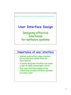
9 This user guide provides information about using, customizing, and simulating a LogiCORE IP DDR3 SDRAM Memory Interface core for 7 Series FPGAs . In the Embedded Development Kit (EDK) this core is provided through the Xilinx Platform Studio (XPS) as the axi_7series_ddrx IP with a static AXI4 to DDR3 SDRAM architecture. The user guide describes the core architecture and provides details on customizing and interfacing to the :The current release of this solution supports DDR3 SDRAM and QDRII+ SRAM Memory FeaturesThe new features in the 7 Series FPGA Memory Interface Solutions are: Higher performance. New hardware blocks used in the physical layer: PHASER_IN and PHASER_OUT, PHY control block, and I/O FIFOs (see Core Architecture, page 48). Pinout rules changed due to the hardware blocks (see design Guidelines, page 102). Controller and user Interface operate at 1/4 the Memory clock Started with the CORE Generator SoftwareThis section is a step-by-step guide for using the CORE Generator software to generate a DDR3 SDRAM Memory Interface in a 7 Series FPGA, run the design through implementation with the Xilinx tools, and simulate the example design using the synthesizable test bench Requirements ISE design Suite, version Series FPGAs Memory Interface SolutionsUG586 March 1, 2011 Chapter 1:DDR3 SDRAM Memory Interface SolutionCustomizing and Generating the CoreGeneration through Graphical user InterfaceThe Memory Interface Generator (MIG) is a self-explanatory wizard tool that can be invoked under the CORE Generator software from XPS.
10 This section is intended to help in understanding the various steps involved in using the MIG steps should be followed to generate a 7 Series FPGA DDR3 SDRAM design :Note:The exact behavior of the MIG tool and the appearance of some pages/options might differ depending on whether the MIG tool is invoked from the CORE Generator software or from XPS, and whether or not an AXI Interface is selected. These differences are described in the steps invoke the MIG tool from XPS, select Memory and Memory Controller AXI 7 Series Memory Controller from the XPS IP catalog (when adding new IP to the system) or right-click the axi_7series_ddrx component in the XPS System Assembly View and select Configure Then skip to MIG Output Options, page , to launch the MIG tool from the CORE Generator software, type mig in the search IP catalog box (Figure 1-1).X-Ref Target - Figure 1-1 Figure 1-1:Xilinx CORE Generator Software7 Series FPGAs Memory Interface March 1, 2011 Getting Started with the CORE Generator File New Project to open the New Project dialog box.