Transcription of 70 Series 4 Post NEMA 2 Enclosure Yale/Lift-Tech Brake ...
1 Bulletin No. BK4725 (3/18). 70 Series 4 Post NEMA 2 Enclosure Yale/Lift-Tech Brake instructions Read carefully before attempting to assemble, install, operate or maintain the product described. Protect yourself and others by observing all safety information. Failure to comply with instructions could result in personal injury and/or property damage! Retain instructions for future reference. When unpacking the Brake , inspect it carefully for damage that may have occurred during transit. WARNING. Brake performance and features must be carefully matched to the requirements of the application. Consideration must be given to torque requirements, especially where an overhauling condition exists, as well as thermal capacity, ambient temperature, atmospheric explosion hazards, type of Enclosure and any other unusual conditions. Improper selection and installation of a Brake and/or lack of maintenance may cause Brake failure which could result in damage to property and/or injury to personnel.
2 If injury to personnel could be caused by Brake failure, additional means must be provided to insure safety of personnel. Do not operate manual release or energize Brake coil before installation, in order to preserve prealignment of rotating discs for ease of installation. Figure 1. DESCRIPTION. This Brake is direct acting, electromagnetically released and spring set. It uses rotating and stationary disc contact to supply positive braking action. It retains quick release and setting capabilities at all times. Simplicity of design has reduced maintenance to an absolute minimum. As with any electromechanical equipment, however, periodic inspec- tion and adjustment will assure optimum performance. As the friction disc wears, the magnet gap will increase. The magnet gap should be checked periodically and adjusted when necessary. SPECIFICATIONS. MOTOR FRAMES - 182TC, 184TC, 213TC, 215TC, 254TC, 256TC. HOUSINGS - Cast iron bracket, stamped steel cover.
3 DUTY - Rated for continuous duty. VOLTAGES - All standard NEMA voltages and frequencies available. Other voltages and frequencies are optional. MOUNTING - Direct to NEMA C motor flanges. Adaptors for larger or smaller frames, foot mounting and vertical mounting are available. ORDERING INFORMATION. The following data should be furnished with your order for: REPLACEMENT PARTS. Brake Model Number Part Number from Tables Part Description from Tables (For electrical parts specify voltage, phase & frequency.). REPLACEMENT Brake . Model Number Voltage, Phase & Frequency Mounting - Horizontal or Vertical. (If vertical, specify whether above or below motor. If Brake includes foot mounting bracket or adaptor, specify.) Figure 2. Wiring Diagram Note: Dings Company does not supply a hub with this style Brake . 4740 WEST ELECTRIC AVENUE l MILWAUKEE, WI 53219 l PHONE 414/672-7830 l FAX 414/672-5354 l www. INSTALLATION MANUAL RELEASE. (See Figures 3, & 5, Tables 2 & 3) (See Figure 5).
4 1. Use existing Brake hub. Hub is not provided by Dings Company. To operate release, rotate two rods(10) clockwise until stop screw (14). 2. Remove cover screws (24) and cover (23). hits pin. Brake will remain in released position until rods are manually 3. Place Brake on motor, guiding discs on hub. returned to original position, or until electrical power is restored which 4. Bolt Brake to motor C face with four socket head cap screws. See automatically returns the release rods to the set position. Figure 3 to determine bolt length. 5. Connect coil leads per appropriate wiring diagram in Figure 2 and replace cover. Figure 3. Exploded View of Brake TORQUE ADJUSTMENT MANUAL RELEASE ASSEMBLY. (See Figures 3 & 5) (See Figure 3). Brake is factory set for rated torque per spring length H . To increase When assembling a standard manual release mechanism (Figure 3), stopping time and lower torque, turn four locknuts (9) counterclockwise, add only enough shim washers (13) to obtain proper release action.
5 Increasing dimension H . All four springs must be set to the same Too many shim washers will prevent automatic reset when electrical length. Do not decrease spring length H as this may cause coil to power is applied. Too few washers will prevent the motor shaft from burn out. turning freely. Replace stop screws (14). Wind each torsion spring (11). approximately 1/4 turn and hook spring loop over pin. WEAR ADJUSTMENT. (See Figures 3 & 5, Table 2) MAGNET COIL REPLACEMENT. Magnet gap D increases as friction discs wear. When gap approaches (See Figures 3 & 4). D max., adjust gap to D min. dimension by turning nuts (21 and Remove magnet assembly as outlined under 22). Magnet gap can vary from nominal + .005 between corners. After FRICTION DISC REPLACEMENT. setting gap, readjust torque spring length H . Coils (18) are held in place with epoxy cement. Force coil off magnet CAUTION: MAGNET GAP MUST NOT EXCEED. mounting plate and remove excess epoxy from all surfaces.
6 D MAXIMUM. Replacement coils should be held in place with new epoxy cement. The epoxy cement should be heat resistant and shock resistant. FRICTION DISC REPLACEMENT Place an insulating washer (19 or 19a) below the coils. Order insulating (See Figures 3 & 5, Table 2) washers when ordering coils. An insulating washer can be cut to suit *When the rotating friction disc (4) wears down to a thickness of 7/32 , when replacing only one coil on a multiple coil assembly. replace disc. 1. Remove cover screws (24) and cover (23). When installing coils, it is very important to follow EXACTLY the 2. Unhook loop of torsion springs (11) from pins at rear of magnet sequence of black and light colored leads as shown in wiring diagram plate (16). Remove release stop screws (14), washers (12) and (Figure 2). The Brake will not operate properly unless coils are all in shims (13). the correct position. 3. Remove adjusting lock nuts (22), magnet assembly (16), adjusting nuts (21), torque nuts (9), washers (8), torque spring (7) and pressure plate (6).
7 4. Remove friction disc (4) and stationary disc (5). Replace worn friction discs. 5. Reassemble all parts in reverse order. Set spring length H and magnet gap D . Assemble manual release. See following paragraph. Figure 4. Fastening of Replacement Magnet Coils Table 1. Parts List ITEM Qty. Description Part Number Number Required 1 Hub (not supplied by Dings Company) N/A. 2 1 Bracket - 1 Disc L070260-001. 2 1 Bracket - 2 Disc L070260-002. 2 1 Bracket - 3 Disc L070260-003. 2 1 Bracket - 4 Disc L070260-004. 3 4 Stud - 1 Disc G070213-001. 3 4 Stud - 2 Disc G070213-002. 3 4 Stud - 3 Disc G070213-003. 3 4 Stud - 4 Disc G070213-004. 4 * Rotating Friction Disc H070103-008. 5 ** Stationary Disc K070474-002. 6 1 Pressure Plate K070307-001. 7 4 Torque Spring (7 lb-ft) G070068-001. 7 4 Torque Spring (19 lb-ft) G070525-001. 7 4 Torque Spring (11, 27, 38, 53 lb-ft) G080192-001. 8 4 Torque Spring Washer W004004-001. 9 4 Torque Adjust Nut W003001-022. 10 2 Manual Rlease Rod G070001-002.
8 11 2 Manual Rlease Spring G060010-001. 12 2 Manual Rlease Washer W004004-003C. 13 As Req'd Manual Release Shim W004004-004C. 14 2 Manual Release Stop Screw G060029-001. 15 2 Manual Release Lockwasher W004007-007. 16 1 Magnet Assembly, Single Phase - includes items 17-20 **. 16 1 Magnet Assembly, Three Phase - includes items 17-19; 230/460V, 3 Phase, 60Hz ** K070339-001. 16 1 Magnet Assembly, Three Phase - includes items 17-19; 200/400V, 3 Phase, 60Hz ** K070339-022. 16 1 Magnet Assembly, Three Phase - includes items 17-19; 115/230V, 3 Phase, 60Hz ** K070339-012. 16 1 Magnet Assembly, Three Phase - includes items 17-19; 287/575V, 3 Phase, 60Hz ** K070339-021. 17 1 Magnet Plate w/o Coils, Single Phase K070352-001. 17a 1 Magnet Plate w/o Coils, Three Phase K070306-001. 18 4 Magnet Coil - Single Phase **. 18a 6 Magnet Coil - Three Phase 230/460V, 3 Phase, 60Hz ** H020003-001. 18a 6 Magnet Coil - Three Phase 200/400V, 3 Phase, 60Hz ** H020003-022.
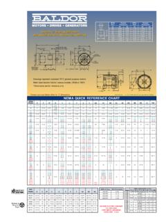
9 18a 6 Magnet Coil - Three Phase 115/230V, 3 Phase, 60Hz ** H020033-012. 18a 6 Magnet Coil - Three Phase 287/575V, 3 Phase, 60Hz ** H020003-021. 19 2 Insulating Washer - Single Phase G070029-001. 20 2 Shading Coil, Single Phase Only G070032-001. 21 4 Gap Adjusting Nut W003003-023. 22 4 Gap Adjusting Nut W003001-020. 23 1 Cover, Standard K070471-001. 24 2 Cover Screw with Lockwasher W001049-006. 25 1 Conduit Hole Plug W008003-001. 26 1 Nameplate Per Order 35 2 Drive Screw W001012-048. *Number of rotating discs is shown as second digit of model number. Example: 72019-54 has 2 rotating discs **Number of stationary discs is one less that the number of rotating discs. **Contact factory for other voltage ratings. Advise Brake model number, voltage rating, and frequency. Table 2. Standard Housing Thermal Inertia Dimensions Model Torque Weight D. Capacity WK2. Number lb-ft lbs C H AC. HPS/MIN Lb-ft2 MAX MIN. 71007-54 7 28 10 .060 .035 71011-54 11 28 10.
10 060 .035 72019-54 19 33 11 .060 .035 72027-54 27 33 11 .065 .040 73038-54 38 38 12 .065 .040 74053-54 53 43 13 .065 .040 Figure 5. Standard Housing TROUBLE SHOOTING. A. IF Brake DOES NOT RELEASE: C. IF Brake CHATTERS OR HUMS: 1. Check Brake visually for broken or damaged parts. 1. See that magnet faces are clean. To remove dirt, insert a clean 2. Check for broken leadwire or bad electrical connection. sheet of paper between magnet faces and energize Brake . 3. Check for correct voltage. Line voltage must correspond to the Move paper around between faces to dislodge dirt, then voltage for which the Brake coils are connected. If the line remove paper. voltage is more than 10% below the voltage for which the 2. Check for low voltage. Magnet will not pull in, and coils will Brake coils are connected, the magnet will not pull in, causing burn out if line voltage is beyond 10% below the voltage the the coils to burn out within minutes. If the line voltage is more Brake coils are connected for.