Transcription of 7100e:7100e marine-appl-manual mdo-hfo - cmar.hk
1 VD 7-100 e MDO and HFO applicationsTable of Instructions42 Technical Flow Meter Flow Meter Flow Meter Application Flow Meter Flow Meter Dimensions (for flange version only) Flow Meter Transducer Dimensions73 Design of measuring comparison of different measurement in differential and / / start up155 Maintenance156 Troubleshooting167 Warranty Disclaimer17 Appendix I. 18 Pressure Drop Curves231. IntroductionThank you for your decision to work with Aquametro fuel Performance Products. This manual describes the installation, commissioning and use of Aquametro s contoil fuel meters . For additional information pleasecontact your local sales agent to be found at: Disclaimer The manufacturer cannot monitor the compliance to this manual as well as the conditions and methods during the installation, operation,usage and maintenance of the system regulator.
2 Improper installation can cause damages and endanger people. Therefore, we assume no responsibility and liability for losses, damagesor costs that result due to incorrect installation, improper operation, usage and maintenance or in any manner associated therewith. Si-milarly, we assume no responsibility for patent right or other right infringements of third parties caused by usage of this system regulator. The manufacturer reserves the right, without prior notification, to make modifications concerning the product, technical data or installa-tion and operating manual . precautionsCONTOIL flow meters must only be used for their intended purpose and comply with local and international safety regulations.
3 All documentation is to be followed exactly. None of the information stated here or elsewhere releases planners, installers and operatorsfrom their own careful and comprehensive assessment of the respective plant configuration in terms of functional capability and opera-tional safety. Local applicable working regulations must be complied with, during all work on the plant and/or ship. All safety-, installation- and operation instruction as described in this manual must be followed. Sensors are sensitive measuring instruments and should be treated carefully. When removing or reinstalling sensors or components from the system, safety instructions in the respective operating manual must befollowed.
4 Extra caution is required, when using inflammable cleaning substances, work space must be ventilated well. The clearance distance of the piping must be adhered to when mounting the meter. If using flanged connections, the correct number ofconnector elements must be fitted and they must be tightened with the correct torque in accordance with the screw manufacturer s in-structions. Always comply with the permissible operating data as specified and mentioned on the type plate. The meter must at all times be completely filled with liquid during operation. Check the meter periodically for tightness of the connections and for proper functioning. Make sure that no hazardous fumes can build up in the piping and in the meter during commissioning, decommissioning and dismant-ling.
5 Prior to disassembly, the measuring instruments must be free from dangerous or noxious residues. Clean and rinse thoroughly! The unit must be installed to VDC and must notbe installed to 110 VAC or 230 VDC. Electrical wiring and installations are subject to statutory regulations, which must be taken into account when planning the system. contoil flow meters are not for installation in zones subject to explosion hazards. Make sure that no hazardous fumes can build up in the piping and in the meter during commissioning, decommissioning and dismant-ling. If work is to be done on the installation, before each intervention:a) Release the pressure in the installationb) If hazardous fluids are used, wear protective clothing and safety goggles.
6 Prior to disassembly, the measuring instruments must be free from dangerous or noxious residues. Clean and rinse thoroughly!c) Place collecting vessel underneath the A/EAuxiliary EngineCFM-SCONTOIL fuel Monitor - ShipCFM-TCONTOIL fuel Monitor - Tug-boatDNDiameter Nominal ECRE ngineering Control RoomEREngineering RoomETO Electro Technical OfficerFM xFuel Meter fuel Performance AnalyserFPM fuel Performance ManagementFPR fuel Performance RecorderPLCP rogrammable Logic Controller GPSG lobal Positioning SystemHFO Heavy fuel OilMDOM arine Diesel OilMGOM arine Gas OilM/EMain EngineMTMain TankPt100 Standard Resistance thermometer (R0 = 100 Ohm)TxTemperature Sensor (Pt100) W/HWheel House (= bridge)
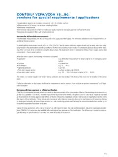
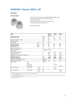
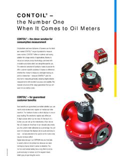
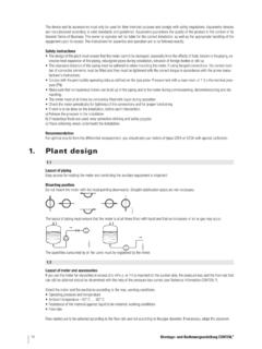
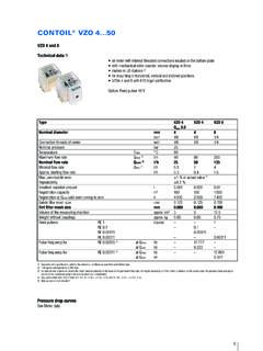
7 InstructionsBedienungsanleitung / Operating instructions / Mode d emploi contoil control: VZF / VZFAArt. No. 2031352. Technical InformationCONTOIL flow meters work on the volumetric principle of rotary piston meters (positive displacement meters ). The main features of thismeasuring principle are large measuring ranges, high accuracy, suitability for high viscosities and independence from power supply; flowdisturbances do not influence proper piston, guide roller and drive are the only moving parts in contact with the liquid. Their movement is transmitted by a magnetic coup-ling through a sealing plate. The hydraulic part is completely separated from the totalising Flow Meter TypesTypeDisplayDisplayed Units AccuracyAccuracyvaluesdisplayedStandardP aired calibrationVZFD igital Display- Total volume- m3 1 % of readingNot available- Resettable Litre % repeatability- Current Flow- US Gallons- Total hrs used- Max.
8 FlowVZFAD igital Display- Total volume- m3 % of reading % supply meter- Resettable Litre % repeatability % return meter- Current Flow- US Gallons- Total hrs used- Max. FlowVZOR oller Counter- Total volume- Litre 1 % of readingNot available- US Gallons % repeatabilityVZOAR oller Counter- Total volume- Litre % of reading % supply meter- US Gallons % repeatability % return Flow Meter MaterialsPartMaterialRemarkHousing with flangesSpheroid graphite iron (GGG)Not in contact with measured fluidMeasuring chamber PN 16 & 25 Cast brassin contact with measured fluidMeasuring chamber PN 40 Stainless Steelin contact with measured fluidSealsFPM fluor-elastomerin contact with measured fluidRotary PistonAnodized aluminiumin contact with measured fluidAncillariesPlastic Not in contact with measured fluidCover of meterPlastic Not in contact with measured fluidColour of housingEnamelled red RAL Flow Meter Application Specifications General specifications, which are same for all type of contoil Flow meters : Minimum ambient temperature: -25 C Maximum ambient temperature.
9 +70 C Maximum viscosity to keep pressure loss 1 bar is 300 cSt To keep the maximum Viscosity below 300 cSt a minimum temperature for different oil types has to be kept: Recommended Min. Temp. for 300 cSt IFO 1000 fuel oil: 90 C Recommended Min. Temp. for 300 cSt IFO 700 fuel oil: 80 C Recommended Min. Temp. for 300 cSt IFO 500 fuel oil: 70 C Recommended Min. Temp. for 300 cSt IFO 380 fuel oil: 60 CGeneral specifications, which are same for all type of contoil Flow meters : Maximum fuel temperature for below listed contoil Flow meters : 180 C Maximum pipe pressure for below listed contoil Flow meters : 25 bar Maximum filter mesh size is given in the table below.
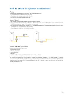
10 In general it is recommended to install the flow meters after the automatic filter, before the engine, which anyway requires a much lower mesh (preferred choise) forArt. filter mesh sizedifferent specs please refer flow ratemax. flow rate*(before flow meter)to our website l/hl/hmmVZF 20 FL 180/25 DIN9371030 1 000 25 FL 180/25 DIN9372775 2 000 40 FL 180/25 DIN93732225 6 000 50 FL 180/25 DIN93736750 20 000 20 FL 180/JIS 20K9411630 1 000 25 FL 180/JIS 20K9411875 2 000 40 FL 180/JIS 20K94120225 6 000 50 FL 180/JIS 20K94122750 20 000 20 FL 180/25 DIN9376030 1 000 25 FL 180/25 DIN9376575 2 000 40 FL 180/25 DIN93770225 6 000 50 FL 180/25 DIN93774750 20 000 20 FL 180/JIS 20K9412430 1 000 25 FL 180/JIS 20K9412675 2 000 40 FL 180/JIS 20K94128225 6 000 50 FL 180/JIS 20K94130750 20 000 20 FL 180/25 DIN9225830 1 000 25 FL 180/25 DIN9226475 2 000 40 FL 180/25 DIN92274225 6 000 50 FL 180/25