Transcription of CONTOIL VZFA/VZOA 450, versions for higher requirements ...
1 15 CONTOIL VZFA/VZOA , versions for higher requirements / applicationsFor applications requiring an increased accuracy of % or better, such as: Measurement of EL heating fuel or diesel in testing facilities Differential measurement Custody transfer, where counters have statutory metrological requirements or calibrationVersions for differential measurementsFor differential measurements, the flow is measured in the supply and return pipes. The difference between the two measurements is re-garded as the obtain optimal measurement results, VZFA or VZOA CONTOIL fuel oil meters calibrated in pairs should only be used, which are adapt-ed precisely to the plant/system operating conditions. The flow rate occurring in each meter, the permissible pressure drop and the viscos-ity of the fluid must all be considered during the design phase. The load on the meter is obtained as follows: flow in supply section less con-sumption = flow in return the order is placed, the following information is required: differential measurement for industrial furnaces fuel diesel fuel C operating 4 bar flow rate in supply fixed pumping rate 200 l/h flow rate in return l/h (for a consumption of l/h)The meters are marked supply and return during calibration and final testing in the factory.
2 They must then be installed in the further information on the subject of differential measurement, see the sections How to obtain an optimal measurement and "Appli-cation examples". versions with type approval or calibrationThese flow meters bear the test number for the metrological type test certificate in accordance with directive 2004/22/EC and the metro-logical CE mark and are therefore suitable for custody transfer. For custody transfer, the meters can only be used for direct consumptionmeasurement and have to be installed between fixed measurement result can be transferred to external meters by means of pulse transmitters or pulse outputs. The transferred measure-ment result is notin line with the directive 2004/22/ and cannotbe used as a legally displayed result. Only the local display of the flow me-ter is valid for custody of useThe CONTOIL flow meter with MID approval is used almost exclusively where the measured liquid (heating oil, diesel) then goes directlyto the consumer (heating system burner).
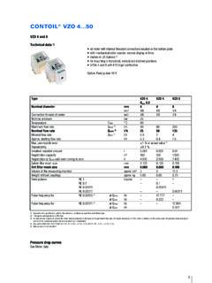
3 Other applications than the described above, must be checked and approved by the local accordance and compliance with the applicable norms for custody transfer, CONTOIL flow meters with MID approval can be data 1) versions for optimal results from differential measurement or for fiscal or commercial transactions VZFA with electronic display of total volume, resettable volume and flow rate; units ofmeasurement: litres, US gallons 2) or m3. VZOA with display of total volume on roller counter; units of measurement: litres. Optional versions with counter in US gallons. VZOA option: with RV reed or IN inductive pulser threaded or flanged connections available mounting in horizontal or vertical positions possible (for calibrated meters horizontally only). VZFA: User-friendly, interactive parameter input. Easy integration into control versions available on request: different flange drillings, such as ANSI, JIS1) Manufacturer's specification, valid for the reference conditions as specified under Meter ) 1 US gallon corresponds to litres3) For burners and engines or motors, the meter must be selected on the basis of the permanent flow rate.
4 For higher viscosities, or if the meter is installed on the suction side, the pressure drop and any reduc-tion in the measuring range must also be taken into ) Min. flow rate VZO 15 with IN-pulser: 15 l/h5) Weight without ) Two freely selectable outputs are available, totally independent of each diameterDNmm1520254050inch1/23/4111/22 Installation lengthmm16 5165190300350 Nominal pressure with threaded ends PNbar16 Nominal pressure with flangesPNbar25 Maximum temperatureTmax C130, 180 Maximum flow rateQmax3)l/h60015003 0009 00030 000 Nominal flow rateQcont3)l/h40010002000600020000 Minimal flow rateQminl/h10 4)3075225750 Approx. starting flow ratel/h4123090300 Max. permissible error< % of actual valueRepeatability %Safety filter mesh filter mesh of the measuring finishenamelled red RAL 3013 Weight with threaded ends 5)approx. Weight with flanges PN 25approx. readable amount:Total volumel, m3No decimalsResettable volumel, m31 decimal placeDigital flow rate displayl/h1 decimal placeRegistration capacityl, m38 digitsRegistration time at Qcontuntil overrunning to zero h128 000 100 00050 00016 6675 000 Outputs 6)Pulse value for totalisorV/Imppulse value and width parameterisableCurrent mA for flow rate I4 / Q1, I20/ Q2flow rates to 4 and 20 mA parameterisableFrequency for flow ratef1/ Q1, f2/ Q2frequency and flowrate parameterisableLimiting value switchQmin, Qmaxminimum, maximum and hysteresis parameterisableVZOAS mallest readable capacitym3100010 00010 00010 000100 000 Registration time at Qcontuntil overrunning to zeroh250010 0005 00016675 000 Pulse values of pulsers:IN inductive according to IEC 60947-5-6 Reedl/pulse1 1010020 Technical data for VZOA with directive 2004/22/CE (MID)Technical data for VZFA with directive 2004/22/CE (MID)Two items are required when ordering.
5 The VZOA or VZFA plus CE-Conformity declaration, Order No. VZOA or VZFA plus legal verification, Order No. ) The meter must be selected on the basis of the permanent flow rate. For higher viscosities, or if the meter is installed on the suction side, the pressure drop and any reduction in the measuring range must al-so be taken into display and Outputs VZFA: see page 6RV Pulsers and IN Pulsers: see page 14 Pressure drop curves: see Meter dataDimensions VZFAD imensions VZOAD etailed dimensional diagrams in Meter dataType designation keyVZOA 25 FL130/25-IN IN or RV and pulse valueNominal pressure (bar)Temperature ( C)Connection (RC = Threaded ends, FL = Flanges)Nominal diameter (mm)Meter typeTypeVZOAVZOAVZOAVZOAVZOA1520254050 Temperature C130 130 130 130 130 Maximum flow rateQmax1)l/h40010002000600020000 Nominal flow rateQcont1)l/h40010002000600020000 Minimal flow rateQminl/h401002006002000 Accuracy permissible error % of actual C130 130 130 130 130 Maximum flow rateQmax 1)l/h40010002000600020000 Nominal flow rateQcont 1)l/h40010002000600020000 Minimal flow rateQminl/h401002006002000 Accuracy permissible error % of actual 15 VZFA 20 VZFA 25 VZFA 40 VZFA 50 Length165165190300350 Width105105130210280 Height155164191243299 TypemmVZOA 15 VZOA 20 VZOA 25 VZOA 40 VZOA 50 Length165165190300350 Width105105130210280 Typ.
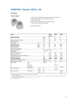
6 130 CHeight 106115142235291 Height -RV 130139166259315 Height -IN 185194221273329 Typ .. 180 CHeight147156183235291 Height -RV 171180207259315 Height -IN 22523426131336921 AccessoriesOrdering details for accessoriesOrder details for supplementary equipment Order details for supplementary equipment with mounting kitsTypeDescriptionOrder calculatorfreely programmable, with analogue output mA, indication of flow rate, limiting valuesDifferential flow calculatorfreely programmable, with analogue mA, indication of flow rate, limiting inputs can be read out current converterfreely kitKit for wall mounting or on DIN-35 mm rail on requestTypeDescriptionOrder switch amplifierEx versionwith relay output, max. 10 Hz81705Ex versionwith electronic output, max. 5 kHz80013 TypeDescriptionOrder connections VSR 1/2 for DN 1581160 VSR 3/4 31/2 for DN 2081163 VSR 3/4 for DN 2081166 VSR 1 for DN 2581169 VSR 11/2 for DN 4081181 Threaded connections kitPS-Kit VZO 41/8 881583 Mounting kitPS-Kit VZO 8 Mounting Kit81130 VSR 3/8 Threaded connections to suit PS-Kit VZO 88115622 Meter dataFunctionCONTOIL flow meters work on the volumetric principle of rotary piston meters (positive displacement meters ).
7 The main features of this measuring principle are large measuring ranges, high accuracy, suitability for high viscosities and independen-ce from power supply; flow disturbances do not influence proper piston, guide roller and drive are the only moving parts in contact with the liquid. Their movement is transmitted by a magnetic cou-pling through a sealing plate. The hydraulic part is completely separated from the totalising 15 .. 50 VZO/VZOA 15 .. 50 VZO/VZOA 4 and 8 Connections are made radially with With the exception of the counter with The connections for the inlet and outlet two cable entries underneath thethe RV Reed pulser, the roller counter are situated vertically from below in thedisplay unit which can be mountedcan be rotated through 360 for base plate. With the OEM meter version theand rotated through 90 are situated on the error limits: Reference conditionsMeasuring error limits according to technical data of meter in % of actual value for the whole measuring conditionsLiquid:Calibration oil similar to extra light heating oil, density at 20 C = 814 kg/m3 Viscosity = mm2/s according to DIN 51757 / ISO 3104 (corresponds to )Temperature: CHorizontal mounting, readings from Oil meters are never to be tested with water, otherwise they will get Qmax+1%0 1%Max.
8 Permissable rate23 Pressure drop curvesViscosity informationKinematic viscosityStokes, Centi-Stokes, mm2/sSt, cSt, mm2/sDynamic viscosityPascal seconds, millipascal secondsPas, , Centipoise (outmoded)P, cPConversioncSt 3density = degrees E to : only use conversion tableSaybolt units to : only use conversion tableRedwood units to : only use conversion tableRule of thumb1cSt 1mm2/s 4DN 8 Viscosity diagrams:A=5 E= 500 a pressure drop of more than 1 bar, it is recommended to use the next larger meter permissible pressure drop = 3 00010001001010,1A0,01 Flow rate in l/h1101001000 Qmin1 l/hQmax80 l/hPressure drop in 000100010010ED1CB0,1A0,01 Flow rate in l/h1101001000 Qmin4 l/hQmax200 l/hPressure drop in rate in l/h 10100100010 000 Qmin30 l/hQmax1500 l/h DN 15DN 20DN 25DN 40 Viscosity diagrams:A=5 E= 200 a pressure drop of more than 1 bar, it is recommended to use the next larger meter permissible pressure drop = 3 bar 0001000100F10 EDC10,1A0,01 Flow rate in l/h 100100010 000100 000 Qmin225 l/hQmax9 000 000100010010 FED1C0,1BA0,01 Flow rate in l/h1101001000 Qmin10 l/hQmax600 l/hPressure drop in 000100010010FE1DC0,1A0,01 Flow rate in l/h10100100010 000 Qmin75 l/hQmax3 000 l/hPressure drop in mbarPressure drop in mbarPressure drop in mbar25DN 0001000100F10ED1C0,1A0,01 Flow rate in l/h 100100010 000100 000 Qmin750 l/hQmax30 000 l/hPressure drop in 000100010010FE1DC0,1A0,01 Flow rate in l/h10100100010 000 Qmin75 l/hQmax3 000 l/hPressure drop in mbarExampleMineral oil, viscosity 450 25 mounted on pressure side of pumps Viscosity curves DN 25select closest curveF = 500 Assume max.
9 Permissible pressure drop = 1 bar The intersection of curve F with the line corre-sponding to 1bar gives a flow rate of 2000 l/h. 28 Dimensions of transducer groups / measurement transducerVZF(A), VZO(A) Dimensional drawings 1 - 7 from table above123 4567 Display / Roller counterVZF / VZFAVZO / VZOA15 VZO / VZOA 20, 25, 40 VZO / VZOA 50x 0,1x 0,01x 1x 0,10m3,x 0,01x 0, flow meterVZF / VZFA VZO 15 - 25 VZO 40 - 50 / VZOA 15 - 50 Max. temperature130/180 C 130 C180 C130 C180 CPulsersall -RV IN -RV IN -RV IN - RV INDimensional drawing12 36547 54654 790416529 Selection of the optimal meter1) Only in accordance with the maximum mesh size of the dirt filter as per technical ) Two freely selectable independent outputs are always available. applicable not applicableApplication noteFor viscosities higher than or for installations on the suction side of a pump, pressure drop and possible limitation of flow rangemust be taken into and suitableDN 4DN 8DN15DN 20DN 25DN 40DN 50 Meter sizesLight heating fuel Medium heating fuel Heavy heating fuel TypeVZF VZO VZO VZFA VZOA VZOA15-50 4-8 15-50 15-50 4-8 15-50 ApplicationDirect consumption measurement Differential measurement Measuring points with metrolog.
10 Approval / calibration (optional) Measuring points with marine type approval (optional) Most frequent areas of useDomestic / industrial burner light/medium oil heavy oil 1) Common applicationsHeating systems High performance furnacesFuel typesLight heating fuel Medium heating fuel Heavy heating fuel Display of flow dataTotal volume Resettable volume Instantaneous flow rate Method of displayLCD Electronic display Total volume display on roller counter Measuring error limits 1 % if actual value 0,5 % of actual value or smaller PTB approvalClass 1 EC approval/verificationClass 1 DN 4 Class DN 8 Outputs 2)Current Digital outputsvolume pulses frequency signal min/max limiting values Pulser (Option)Inductive, with decadic pulse value Reed pulser for remote totalisation