Transcription of 4419def contoil - Distributor of flow meters for water ...
1 14 Montage- und Bedienungsanleitung contoil designThe device and its accessories must only be used for their intended purpose and comply with safety regulations. Aquametro devicesare manufactured according to valid standards and guidelines. Aquametro guarantees the quality of the product in the context of itsGeneral Terms of Business. The owner or operator will be liable for the correct installation as well as the appropriate handling of theequipment upon its receipt. The instructions for assembly and operation are to be followed instructions The design of the plant must ensure that the meter cannot be damaged, especially from the effects of frost, torsion in the piping, ex-cessive heat expansion of the piping, misaligned pipes during installation, intrusion of foreign bodies or silt-up.
2 The clearance distance of the piping must be adhered to when mounting the meter. If using flanged connections, the correct num-ber of connector elements must be fitted and they must be tightened with the correct torque in accordance with the screw manu-facturer s instructions. Comply with the permissible operating data as defined on the type plate. Pressure test with a maxi-mum of x the nominal pres-sure (PN). Make sure that no hazardous fumes can build up in the piping and in the meter during commissioning, decommissioning and dis-mantling. The meter must at all times be completely filled with liquid during operation.
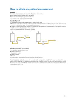
3 Check the meter periodically for tightness of the connections and for proper functioning. If work is to be done on the installation, before each intervention:a) Release the pressure in the installationb) If hazardous fluids are used, wear protective clothing and safety gogglesc) Place collecting vessel underneath the optimal results from the differential measurement, you should only use meters of types VZEA or VZOA with special of pipingEasy access for reading the meter and controlling the ancillary equipment is positionDo not mount the meter with the head pointing downwards. Straight stabilisation pipes are not layout of piping must ensure that the meter is at all times filled with liquid and that no inclusions of air or gas may quantities consumed by all the users must be registered by the of meter and accessoriesIf you use the meter for viscosities in excess of 5 , or if it is mounted on the suction side, the pressure loss and the flow rate thatcan still be attained should be determined with the help of the pressure loss curves (see Technical Information contoil ).
4 Select the meter and the ancillaries according to the max. working conditions. Operating pressure and temperature Ambient temperature 10 C .. 60 C Resistance of the material against: liquid to be metered, working conditions Flow rateFlow meters are to be selected according to the flow rate and not according to the pipe diameter. If necessary, adapt the and operating instructions contoil off devicesIn order to avoid backflows and drainings, shut off devices have to be mounted after the and drainings cause measuring errors and can damage the in plant or liquidFilters should be fitted to prevent any damage caused by impurities in the liquid.
5 * Consider filter mounted in the meter inlet is only a safety filter and is too small to act as a , dosingFor filling and dosing the valve has to be mounted between meter and shorter the pipe section between valve and discharge, the higher the accuracy. Fast opening and shutting of the valve should beavoided (pressure hammer). Pressure hammers damage the processing, ancillariesAny backflow must be avoided on meters equipped with pulsers for remote this cannot be achieved by appropriate plant design, a non-return valve should be circuitElectrical circuits and installations are subject to legal prescriptions which must be observed when planning the installations must only be executed by professional the layout of the installation, the following factors should be taken into account during plant design.
6 Ancillary connected to or after the meter maximum cable lengths with/without amplifier connection boxes, cable guides environmental disturbancesElectrical installations are subject to special mesh width for strainersNominalMeter typewidthVZEVZOVZEAVZOADN150,250 mm0,250 mm0,100 mm0,100 mmDN200,400 mm*0,400 mm*0,100 mm0,100 mmDN250,400 mm*0,400 mm*0,250 mm0,250 mmDN400,600 mm0,600 mm0,250 mm0,250 mmDN500,600 mm0,600 mm0,250 mm0,250 and operating instructions contoil 2. of mountingEasy access for reading the meter and controlling ancillary equipment is the operating temperature range ( 10 C .. 60 C).The meter may not be packed up in thermal plant conception points.
7 The differential measurement on meters VZEA and VZOA, please make sure that each meter is mounted in the correct pipe (supplyflow meter in the supply pipe to the consumer, return flow meter in the return pipe). position acccording to point for the mountingCheck meters and mounting the data of the meter with the expected maximum conditions in the installation. They may not exceed the meter data: Flow rate max. (Qmaxl/h) Service pressure max. (PN bar) Temperature max. (T) Threaded connections, flanges and seals (gaskets) Fixations for the meter Resistance to measured liquid and in case of modifying an existing plant:Rinse previously the installation and put it out of service.
8 Close the valves shutting the insertion sure that a starting-up by other persons is impossible while handling matters hazardous to people protect absolutely eyes, skin and a collecting trough under the chemicals, oils or other matter dangerous to the environment may reach neither the water nor the the pipeline and prepare it for the insert of the flow case of welding, cutting and grinding pay attention to the risk of inflammable matter and liquids from the place of the pipe section for the length prescribed for the measuring unit (see 8. dimensional sketches).When using copper- or thinwalled steel tubes fasten the meter the strainer/pre-filter, if necessary a distance the installation into operation.
9 Open the shut valves to a pressure and tightness the installation the pressure and put the installation out of and operating instructions contoil of the meter into the pipeline, pressure checkWhen mounting the meter into the pipeline pay attention to point protection plugs on the of heavy fuel oil with VZE/VZO 20 or 25:If a strainer with a mesh width of max. mm is installed, the safety filter may be removed from the meter the meter into the pipeline in the prescribed position and flow mating flanges parallel and without bias in with threaded endsMeter with flangesIf another pressure test is done after mounting the meter, following pressure is admitted for a short period:Nominal pressure (PN) test load 16 bar25 bar25 bar40 bar40 bar64 barOperating start as described in point connectionsPay attention to plant design point main plug and fuses.
10 Before working on electrical circuits make sure that nobody can put the installation under attention to installation instructions for electric units: power data, operation data maximum transmission length cable cross section, length ambient temperature, mounting Electrical diagram, technical data for pulsersPulse transmitter type RVCable 3 mPolarity choice free ambient temperature 10 C .. 70 C switching elementReed contact switching voltagemax. 48 V DC/AC switching currentmax. 50 mA (Ri 47 1) switching capacitymax. 2 W static currentnil pulse valuesee type plate Pulse transmitter type IN and INAPay attention to polarity when connecting the plug.