Transcription of 8-bit Microcontroller with 8K Bytes In-System Programmable ...
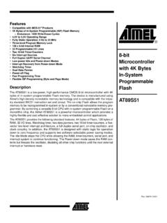
1 1 Features Compatible with MCS-51 Products 8K Bytes of In-System Programmable (ISP) Flash Memory Endurance: 1000 Write/Erase Cycles to Operating Range Fully Static Operation: 0 Hz to 33 MHz Three-level Program Memory Lock 256 x 8-bit Internal RAM 32 Programmable I/O Lines Three 16-bit Timer/Counters Eight Interrupt Sources Full Duplex UART Serial Channel Low-power Idle and Power-down Modes Interrupt Recovery from Power-down Mode Watchdog Timer Dual Data Pointer Power-off FlagDescriptionThe AT89S52 is a low-power, high-performance CMOS 8-bit Microcontroller with 8 Kbytes of In-System Programmable Flash memory. The device is manufactured usingAtmel s high-density nonvolatile memory technology and is compatible with the indus-try-standard 80C51 instruction set and pinout. The on-chip Flash allows the programmemory to be reprogrammed In-System or by a conventional nonvolatile memory pro-grammer. By combining a versatile 8-bit CPU with In-System Programmable Flash ona monolithic chip, the Atmel AT89S52 is a powerful Microcontroller which provides ahighly-flexible and cost-effective solution to many embedded control AT89S52 provides the following standard features: 8K Bytes of Flash, 256 bytesof RAM, 32 I/O lines, Watchdog timer, two data pointers, three 16-bit timer/counters, asix-vector two-level interrupt architecture, a full duplex serial port, on-chip oscillator,and clock circuitry.
2 In addition, the AT89S52 is designed with static logic for operationdown to zero frequency and supports two software selectable power saving Idle Mode stops the CPU while allowing the RAM, timer/counters, serial port, andinterrupt system to continue functioning. The Power-down mode saves the RAM con-tents but freezes the oscillator, disabling all other chip functions until the next interruptor hardware 1919A-07/018-bit Microcontroller with 8K Bytes In-System Programmable FlashAT 8 9 S 5 2AT89S522 TQFP123456789101133323130292827262524234 4434241403938373635341213141516171819202 122(MOSI) (MISO) (SCK) (RXD) (TXD) (INT0) (INT1) (T0) (T1) (AD4) (AD5) (AD6) (AD7)EA/ (A15) (A14) (A13) (T2 EX) (T2) (AD0) (AD1) (AD2) (AD3)(WR) (RD) (A8) (A9) (A10) (A11) (A12) (MOSI) (MISO) (SCK) (RXD) (TXD) (INT0) (INT1) (T0) (T1) (AD4) (AD5) (AD6) (AD7)EA/ (A15) (A14) (A13)65432144434241401819202122232425262 728(WR) (RD) (A8) (A9) (A10) (A11) (A12) (T2 EX) (T2) (AD0) (AD1) (AD2) (AD3)Pin ConfigurationsPDIP1234567891011121314151 6171819204039383736353433323130292827262 524232221(T2) (T2 EX) (MOSI) (MISO) (SCK) (RXD) (TXD) (INT0) (INT1) (T0) (T1) (WR)
3 (RD) (AD0) (AD1) (AD2) (AD3) (AD4) (AD5) (AD6) (AD7)EA/ (A15) (A14) (A13) (A12) (A11) (A10) (A9) (A8)AT89S523 Block DiagramPORT 2 DRIVERSPORT - 0 LATCHRAMPROGRAMADDRESSREGISTERBUFFERPCIN CREMENTERPROGRAMCOUNTERDUAL DPTRINSTRUCTIONREGISTERBREGISTERINTERRUP T, SERIAL PORT,AND TIMER BLOCKSSTACKPOINTERACCTMP2 TMP1 ALUPSWTIMINGANDCONTROLPORT 1 - 3 LATCHPORT 3 - / VPPRSTRAM 0 - 1 LATCHWATCHDOGISPPORTPROGRAMLOGICAT89S524 Pin DescriptionVCCS upply 0 Port 0 is an 8-bit open drain bidirectional I/O port. As anoutput port, each pin can sink eight TTL inputs. When 1sare written to port 0 pins, the pins can be used as high-impedance inputs. Port 0 can also be configured to be the multiplexed low-order address/data bus during accesses to externalprogram and data memory. In this mode, P0 has 0 also receives the code Bytes during Flash program-ming and outputs the code Bytes during program verifica-tion.
4 External pullups are required during programverification. Port 1 Port 1 is an 8-bit bidirectional I/O port with internal Port 1 output buffers can sink/source four TTL 1s are written to Port 1 pins, they are pulled high bythe internal pullups and can be used as inputs. As inputs,Port 1 pins that are externally being pulled low will sourcecurrent (IIL) because of the internal pullups. In addition, and can be configured to be thetimer/counter 2 external count input ( ) and thetimer/counter 2 trigger input ( ), respectively, asshown in the following 1 also receives the low-order address Bytes duringFlash programming and 2 Port 2 is an 8-bit bidirectional I/O port with internal Port 2 output buffers can sink/source four TTL 1s are written to Port 2 pins, they are pulled high bythe internal pullups and can be used as inputs. As inputs,Port 2 pins that are externally being pulled low will sourcecurrent (IIL) because of the internal 2 emits the high-order address byte during fetchesfrom external program memory and during accesses toexternal data memory that use 16-bit addresses (MOVX In this application, Port 2 uses strong internal pul-lups when emitting 1s.)
5 During accesses to external datamemory that use 8-bit addresses (MOVX @ RI), Port 2emits the contents of the P2 Special Function 2 also receives the high-order address bits and somecontrol signals during Flash programming and 3 Port 3 is an 8-bit bidirectional I/O port with internal Port 3 output buffers can sink/source four TTL 1s are written to Port 3 pins, they are pulled high bythe internal pullups and can be used as inputs. As inputs,Port 3 pins that are externally being pulled low will sourcecurrent (IIL) because of the 3 also serves the functions of various special featuresof the AT89S52, as shown in the following 3 also receives some control signals for Flash pro-gramming and input. A high on this pin for two machine cycles whilethe oscillator is running resets the device. This pin drivesHigh for 96 oscillator periods after the Watchdog times DISRTO bit in SFR AUXR (address 8EH) can be usedto disable this feature. In the default state of bit DISRTO,the RESET HIGH out feature is Latch Enable (ALE) is an output pulse for latchingthe low byte of the address during accesses to externalmemory.
6 This pin is also the program pulse input (PROG)during Flash programming. In normal operation, ALE is emitted at a constant rate of1/6 the oscillator frequency and may be used for externaltiming or clocking purposes. Note, however, that oneALE pulse is skipped during each access to external datamemory. If desired, ALE operation can be disabled by setting bit 0 ofSFR location 8EH. With the bit set, ALE is active only dur-ing a MOVX or MOVC instruction. Otherwise, the pin isPort PinAlternate (external count input to Timer/Counter 2), (Timer/Counter 2 capture/reload trigger and direction control) (used for In-System Programming) (used for In-System Programming) (used for In-System Programming)Port PinAlternate (serial input port) (serial output port) (external interrupt 0) (external interrupt 1) (timer 0 external input) (timer 1 external input) (external data memory write strobe) (external data memory read strobe)AT89S525weakly pulled high.
7 Setting the ALE-disable bit has noeffect if the Microcontroller is in external execution Store Enable (PSEN) is the read strobe to exter-nal program memory. When the AT89S52 is executing code from external pro-gram memory, PSEN is activated twice each machinecycle, except that two PSEN activations are skipped duringeach access to external data memory. EA/VPPE xternal Access Enable. EA must be strapped to GND inorder to enable the device to fetch code from external pro-gram memory locations starting at 0000H up to , however, that if lock bit 1 is programmed, EA will beinternally latched on reset. EA should be strapped to VCC for internal program pin also receives the 12-volt programming enable volt-age (VPP) during Flash to the inverting oscillator amplifier and input to theinternal clock operating from the inverting oscillator 1. AT89S52 SFR Map and Reset Values0F8H0 FFH0F0HB000000000F7H0E8H0 EFH0E0 HACC000000000E7H0D8H0 DFH0D0 HPSW000000000D7H0C8HT2 CON00000000T2 MODXXXXXX00 RCAP2L00000000 RCAP2H00000000TL200000000TH2000000000 CFH0C0H0C7H0B8 HIPXX0000000 BFH0B0HP3111111110B7H0A8 HIE0X0000000 AFH0A0HP211111111 AUXR1 XXXXXXX0 WDTRSTXXXXXXXX0A7H98 HSCON00000000 SBUFXXXXXXXX9FH90HP11111111197H88 HTCON00000000 TMOD00000000TL000000000TL100000000TH0000 00000TH100000000 AUXRXXX00XX08FH80HP011111111SP00000111DP 0L00000000DP0H00000000DP1L00000000DP1H00 000000 PCON0 XXX000087 HAT89S526 Special Function RegistersA map of the on-chip memory area called the Special Func-tion Register (SFR)
8 Space is shown in Table that not all of the addresses are occupied, and unoc-cupied addresses may not be implemented on the accesses to these addresses will in general returnrandom data, and write accesses will have an indetermi-nate software should not write 1s to these unlisted loca-tions, since they may be used in future products to invokenew features. In that case, the reset or inactive values ofthe new bits will always be 2 Registers: Control and status bits are contained inregisters T2 CON (shown in Table 2) and T2 MOD (shown inTable 3) for Timer 2. The register pair (RCAP2H, RCAP2L)are the Capture/Reload registers for Timer 2 in 16-bit cap-ture mode or 16-bit auto-reload Registers: The individual interrupt enable bitsare in the IE register. Two priorities can be set for each ofthe six interrupt sources in the IP 2. T2 CON Timer/Counter 2 Control RegisterT2 CON Address = 0C8 HReset Value = 0000 0000 BBit AddressableBitTF2 EXF2 RCLKTCLKEXEN2TR2C/T2CP/RL276543210 SymbolFunctionTF2 Timer 2 overflow flag set by a Timer 2 overflow and must be cleared by software.
9 TF2 will not be set when either RCLK = 1 or TCLK = 2 external flag set when either a capture or reload is caused by a negative transition on T2EX and EXEN2 = 1. When Timer 2 interrupt is enabled, EXF2 = 1 will cause the CPU to vector to the Timer 2 interrupt routine. EXF2 must be cleared by software. EXF2 does not cause an interrupt in up/down counter mode (DCEN = 1).RCLKR eceive clock enable. When set, causes the serial port to use Timer 2 overflow pulses for its receive clock in serial port Modes 1 and 3. RCLK = 0 causes Timer 1 overflow to be used for the receive clock enable. When set, causes the serial port to use Timer 2 overflow pulses for its transmit clock in serial port Modes 1 and 3. TCLK = 0 causes Timer 1 overflows to be used for the transmit 2 external enable. When set, allows a capture or reload to occur as a result of a negative transition on T2EX if Timer 2 is not being used to clock the serial port. EXEN2 = 0 causes Timer 2 to ignore events at control for Timer 2.
10 TR2 = 1 starts the or counter select for Timer 2. C/T2 = 0 for timer function. C/T2 = 1 for external event counter (falling edge triggered).CP/RL2 Capture/Reload select. CP/RL2 = 1 causes captures to occur on negative transitions at T2EX if EXEN2 = 1. CP/RL2 = 0 causes automatic reloads to occur when Timer 2 overflows or negative transitions occur at T2EX when EXEN2 = 1. When either RCLK or TCLK = 1, this bit is ignored and the timer is forced to auto-reload on Timer 2 Data Pointer Registers: To facilitate accessing bothinternal and external data memory, two banks of 16-bitData Pointer Registers are provided: DP0 at SFR addresslocations 82H-83H and DP1 at 84H-85H. Bit DPS = 0in SFR AUXR1 selects DP0 and DPS = 1 selects user should always initialize the DPS bit to theappropriate value before accessing the respective DataPointer Off Flag: The Power Off Flag (POF) is located at bit4 ( ) in the PCON SFR. POF is set to 1 duringpower up.