Transcription of 802.11n Wi-Fi Access Point - Ubiquiti Networks
1 Wi-Fi Access PointModels: UAP, UAP-LR (Long-Range)IntroductionThank you for purchasing the Ubiquiti Networks UniFi AP. This Quick Start Guide is designed to guide you through installation and also includes warranty ContentsUniFi APMounting BracketCeiling Backing PlateFlat Head Screws (M3x50, Qty. 3)Keps Nuts (M3, Qty. 3)Screws ( , Qty. 3)Screw Anchors (M3x20, Qty. 3) Wi-Fi Access PointModels: UAP, UAP-LR (Long-Range)PoE Adapter (24V, ) with Mounting BracketPower CordQuick Start GuideInstallation Requirements CAT5/6 cable Phillips screwdriver Drill and drill bit (6 mm for wall-mounting or 3 mm for ceiling-mounting) Optional: Drywall or keyhole saw (to cut 25 mm hole for Ethernet cable feed)TERMS OF USE: All Ethernet cabling runs must use CAT5 (or above). It is the customer s responsibility to follow local country regulations, including operation within legal frequency channels, output power, and Dynamic Frequency Selection (DFS) Requirements Microsoft Windows 7/8, Mac OS X, or Linux Java Runtime Environment (or above) Web Browser: Mozilla Firefox, Google Chrome, or Microsoft Internet Explorer 8 (or above) UniFi Controller software (available at.)
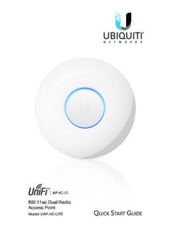
2 Network Topology Requirements A DHCP-enabled network (for the AP to obtain an IP address as well as for the wireless clients after deployment) A management station computer running the UniFi Controller software, located either on-site and connected to the same Layer-2 network, or off-site in a cloud or NOCorNetwork HealthwwwWANLANWLANVOIPwwwWANLANWLANVOIP IPDNSGATEWAYACTIVE CLIENTSDOWNUPSWITCHESUSERSGUESTSDOWNUPAP SUSERSGUESTSDOWNUPPHONESEXTENSIONCALLS INCALLS SITED efaultREFRESH RATE2 minutesNetwork HealthwwwWANLANWLANVOIPwwwWANLANWLANVOIP IPDNSGATEWAYACTIVE CLIENTSDOWNUPSWITCHESUSERSGUESTSDOWNUPAP SUSERSGUESTSDOWNUPPHONESEXTENSIONCALLS INCALLS SITED efaultREFRESH RATE2 minutesO -SiteCloud/NOC 2On-SiteManagementStationUniFi SwitchUniFiSecurityGatewayInternetLANWAN W ired UAP/UAP-LRWirelessUplinked1 UAP/UAP-LR1 GSample Network Diagram1.
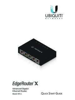
3 To set up wireless-uplinked APs, refer to the User Guide on the website: All UniFi devices support off-site management controllers. See the User Guide for setup OverviewLEDsLED ColorStatusFlashing AmberFactory default, waiting to be Amber/GreenDevice is busy; do not touch or unplug it. This usually indicates that a process such as a firmware upgrade is taking Flashing GreenThis is used to locate an AP. When you click Locate in the UniFi Controller software, the AP will flash. It will also display the location of the AP on the GreenIndicates the device has been successfully integrated into a network and is working Green with occasional flashingIndicates the device is in an isolated state (all WLANs are brought down until an uplink is found).PortsEthernet PortReset ButtonLocking NotchEthernet The 10/100 Ethernet port is used to connect the power and should be connected to the LAN and DHCP server.
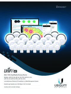
4 Power can be provided by any of the following: Included PoE Adapter Ubiquiti Networks UniFi Switch Ubiquiti Networks TOUGHS witch PROR eset The Reset button serves two functions for the UniFi AP: Restart Press and release the Reset button quickly. Restore to Factory Default Settings Press and hold the Reset button for more than five seconds until the LED turns Clip Mounting BracketLocking Clip During installation, the Locking Clip on the Mounting Bracket locks into the Locking Notch on the UniFi AP to help prevent InstallationThe UniFi AP can be mounted to the wall or ceiling. Perform the steps for the appropriate installation:Wall Mount1. Position the Mounting Bracket at the desired location on the wall with the cable feed slot pointed towards the Use a pencil to mark the three holes on the wall. Use a 6 mm drill bit to drill the 25 mm Hole for Ethernet Cable Feed through Wall3.
5 If your Ethernet cable feeds through the wall, cut or drill a circle approximately 25 mm in diameter, just below the bottom center of the Mounting Bracket (as shown above). Then feed the CAT5/6 cable through the hole.*640-00203-01*640-00203-014. Insert the Screw Anchors into the 6 mm holes. Secure the Mounting Bracket to the wall by inserting the Screws into the Connect the Ethernet cable to the Ethernet Align the notch on the UniFi AP with the notch on the Mounting Turn the UniFi AP clockwise until it locks into Mount1. Remove the ceiling Place the Mounting Bracket in the center of the ceiling tile. Mark the three mounting screw holes and 25 mm hole for the Ethernet mm Hole for Ethernet Cable Feed3. Use a 3 mm drill bit to drill the screw holes, and cut or drill the 25 mm hole for the Ethernet cable Secure the Mounting Bracket to the ceiling tile using the Ceiling Backing Plate, Flathead Screws, and Keps Nuts.
6 Then feed the Ethernet cable through the 25 mm Connect the Ethernet cable to the Ethernet Align the notch on the UniFi AP with the notch on the Mounting Turn the UniFi AP clockwise until it locks into Set the ceiling tile back into the UniFi APThe UniFi AP can be powered directly by a Ubiquiti Networks TOUGHS witch or UniFi Switch, or with the included PoE : The UniFi AP uses passive PoE. You must therefore manually enable 24V passive PoE on the Switch. Connecting to a TOUGHS witchConnect the Ethernet cable from the UniFi AP s Ethernet port directly to a PoE port on the PRO Power Connection DiagramConnecting to a UniFi SwitchConnect the Ethernet cable from the UniFi AP s Ethernet port directly to a PoE port on the UniFi Switch. 1 3 5 7 9 11 13 15 17 19 21 222 4 6 8 10 12 14 16 18 20 22 24 SPF1 SPF2 UniFi Switch Power Connection DiagramConnecting Power over Ethernet1.
7 Connect the Ethernet cable from the UniFi AP s Ethernet port to the adapter s POE Connect an Ethernet cable from your LAN to the adapter s LAN port. 3. Connect the Power Cord to the adapter s power port. Connect the other end of the Power Cord to a power the PoE Adapter (Optional)1. Remove the PoE Mounting Bracket from the adapter, place the bracket at the desired location, and mark the two holes. 2. Pre-drill the holes if necessary, and secure the bracket using two fasteners (not included).3. Align the adapter s slots with the tabs of the PoE Mounting Bracket, and then slide the adapter InstallationDownload and install the latest version of the UniFi Controller software at Launch the software and follow the on-screen instructions. Step-by-step instructions are available in the User Guide located on our website: you have installed the software and run the UniFi Installation Wizard, a login screen will appear for the UniFi Controller management interface.
8 Enter the Admin Name and Password that you created and click Login. You can manage your wireless network and view network statistics using the UniFi Controller management interface. For information on configuring and using the UniFi Controller software, refer to the User x 200 x mm ( x x ")Weight290 g (430 g with Mounting Kits) oz ( oz with Mounting Kits)Networking Interface(1) 10/100 Ethernet PortButtonsResetAntennas2 Integrated (Supports 2x2 MIMO with Spatial Diversity) Wi-Fi b/g/n ( GHz)Power MethodPassive Power over Ethernet (12-24V)Power Supply24V, PoE Adapter (Included)BSSIDUp to Four per RadioPower SaveSupportedWireless SecurityWEP, WPA-PSK, WPA-Enterprise (WPA/WPA2, TKIP/AES)CertificationsCE, FCC, ICMountingWall/Ceiling (Kits Included)Operating Temperature-10 to 70 C (14 to 158 F)Operating Humidity5 to 80% NoncondensingMax.
9 Power ConsumptionUAPUAP-LR4W6 WMax. TX PowerUAPUAP-LR20 dBm27 dBmSafety Notices1. Read, follow, and keep these Heed all Only use attachments/accessories specified by the : Do not use this product in location that can be submerged by water. WARNING: Avoid using this product during an electrical storm. There may be a remote risk of electric shock from lightning. Electrical Safety Information1. Compliance is required with respect to voltage, frequency, and current requirements indicated on the manufacturer s label. Connection to a different power source than those specified may result in improper operation, damage to the equipment or pose a fire hazard if the limitations are not There are no operator serviceable parts inside this equipment. Service should be provided only by a qualified service This equipment is provided with a detachable power cord which has an integral safety ground wire intended for connection to a grounded safety Do not substitute the power cord with one that is not the provided approved type.
10 Never use an adapter plug to connect to a 2-wire outlet as this will defeat the continuity of the grounding wire. b. The equipment requires the use of the ground wire as a part of the safety certification, modification or misuse can provide a shock hazard that can result in serious injury or Contact a qualified electrician or the manufacturer if there are questions about the installation prior to connecting the Protective earthing is provided by Listed AC adapter. Building installation shall provide appropriate short-circuit backup Protective bonding must be installed in accordance with local national wiring rules and WarrantyUBIQUITI Networks , Inc ( Ubiquiti Networks ) warrants that the product(s) furnished hereunder (the Product(s) ) shall be free from defects in material and workmanship for a period of one (1) year from the date of shipment by Ubiquiti Networks under normal use and operation.