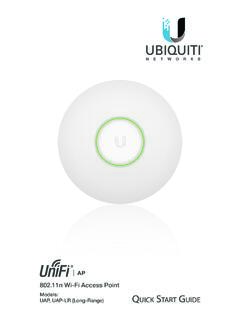
Transcription of 802.11ac Dual Radio Access Point
1 dual Radio Access PointModel: UAP-AC-LITEI ntroductionThank you for purchasing the Ubiquiti Networks UniFi AP. This quick start guide is designed to guide you through installation and includes warranty : The UAP-AC-LITE requires the UniFi Controller or newer, available at: ContentsUniFi AP AC LiteMounting BracketCeiling Backing PlateFlat Head Screws (Qty. 4)Keps Nuts (Qty. 4)Screws (Qty. 4)Screw Anchors (Qty. 4) dual Radio Access PointModel: UAP-AC-LITEG igabit PoE (24V, ) with Mounting BracketPower Cord* quick start GuideInstallation Requirements Phillips screwdriver Drill and drill bit (6 mm for wall-mounting or 3 mm for ceiling-mounting) Optional: Drywall or keyhole saw (to cut 18 mm hole for Ethernet cable feed) Cat5/6 UTP cable for indoor installationsTERMS OF USE: Ubiquiti Radio devices must be professionally installed. Shielded Ethernet cable and earth grounding must be used as conditions of product warranty. TOUGHC able is designed for outdoor installations.
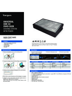
2 It is the professional installer s responsibility to follow local country regulations, including operation within legal frequency channels, output power, and Dynamic Frequency Selection (DFS) Requirements Linux, Mac OS X, or Microsoft Windows 7/8/10 Java Runtime Environment (or above) Web Browser: Google Chrome (Other browsers may have limited functionality). UniFi Controller software or newer (available at: )Network Topology Requirements A DHCP-enabled network (for the AP to obtain an IP address as well as for the wireless clients after deployment) A UniFi Cloud Key or management station running the UniFi Controller software, located either on-site and connected to the same Layer-2 network, or off-site in the cloud or a NOCUS-16-150 WUSG-PRO-4(DHCP Server)InternetUAP-AC-LiteUAP-AC-M-PROUA P-AC-HDLANWANUniFi Cloud Key(UniFi Controller)Remote Access tooUniFi ControllerrSample Network DiagramAll UniFi devices support off-site management controllers. For setup details, see the User guide on the website: OverviewLEDLED ColorStatusWhiteFactory default, waiting to be WhiteInitializing.
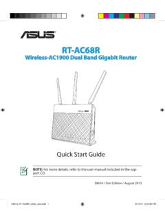
3 Alternating White/BlueDevice is busy; do not touch or unplug it. This usually indicates that a process such as a firmware upgrade is taking the device has been successfully integrated into a network and is working properly. Quickly Flashing BlueThis is used to locate an AP. When you click Locate in the UniFi Controller software, the LED on the AP will flash. It will also display the location of the AP on the Blue with occasional flashingIndicates the device is in an isolated state (all WLANs are brought down until an uplink is found).PortsEthernet Port Reset ButtonLocking NotchCable Feed PlugLocking Notch The Locking Notch will be used with the Mounting Bracket to help secure the UniFi AP. (This is described further in the Mounting Bracket section.)Ethernet This Gigabit Ethernet port is used to connect the power and should be connected to the LAN and DHCP server. Power can be provided by a Ubiquiti Networks UniFi Switch with PoE or Gigabit PoE adapter (included with single-pack only).
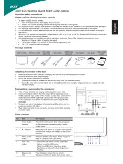
4 Reset The Reset button serves two functions for the UniFi AP: Restart Press and release the Reset button quickly. Restore to Factory Default Settings Press and hold the Reset button for more than five , the UniFi AP may be reset remotely via a Reset button located on the bottom of the Gigabit PoE Feed Plug If your Ethernet cable feeds along the mounting surface, remove the Cable Feed BracketMounting BracketLocking TabLocking Tab During installation, the Locking Tab on the Mounting Bracket moves from the Initial Position to the Final Position, where the Locking Tab fits securely into the Locking Notch on the UniFi AP to help prevent PositionFinal PositionSlotNote: If you need to remove the UniFi AP from the Mounting Bracket, insert a paper clip in the Slot to release the Locking Tab and turn the UniFi AP InstallationThe UniFi AP can be mounted on the wall or ceiling. Perform the steps for the appropriate installation:Wall Mount1. Position the Mounting Bracket at the desired location on the wall with the arrow pointing Use a pencil to mark the four mounting holes.
5 Use a 6 mm drill bit to drill the mounting If your Ethernet cable feeds through the wall, then cut or drill a circle approximately 18 mm in diameter. Then feed the CAT5/6 cable through the mmNote: 25 mm is the distance from the center of the bottom mounting hole to the center of the cable Insert the Screw Anchors into the 6 mm holes. Secure the Mounting Bracket to the wall by inserting the Screws into the If the Ethernet cable runs along the mounting surface, remove the Cable Feed Connect the Ethernet cable to the Ethernet port. 7. Align the arrow on the UniFi AP with the arrow on the Locking Tab of the Mounting Tab8. Ensure that the UniFi AP is firmly seated on the Mounting Bracket. Turn the UniFi AP clockwise until it locks into place and the Locking Tab fits securely into the Locking Mount1. Remove the ceiling Place the Ceiling Backing Plate in the center of the ceiling tile. Mark the four mounting screw Mark a hole approximately 18 mm in diameter for the Ethernet cable mmNote: 25 mm is the distance from the center of the bottom mounting hole to the center of the cable Use a 3 mm drill bit to drill the screw holes, and cut or drill the hole for the Ethernet cable Insert the Flat Head Screws through the Mounting Bracket, ceiling tile, and Ceiling Backing Plate.
6 Fasten the screws using the Keps Nuts. Then feed the Ethernet cable through the 18 mm Connect the Ethernet cable to the Ethernet Align the arrow on the UniFi AP with the arrow on the Locking Tab of the Mounting TabArrow8. Ensure that the UniFi AP is firmly seated on the Mounting Bracket. Turn the UniFi AP clockwise until it locks into place and the Locking Tab fits securely into the Locking Set the ceiling tile back into the UniFi APUse a UniFi Switch with PoE or a Gigabit PoE adapter for power. Connecting to a UniFi Switch with PoEConnect the Ethernet cable from the UniFi AP directly to a PoE port on the UniFi Switch with 3 5 7 9 11 13 15 17 19 21 222 4 6 8 10 12 14 16 18 20 22 24 SPF1 SPF2*640-00180-08*640-00180-08 Connecting Power over EthernetThe single-pack of the UAP-AC-LITE includes one Gigabit PoE adapter.
7 For multi-pack units, we recommend using a UniFi Switch with Connect the Ethernet cable from the device to the adapter s POE Connect an Ethernet cable from your LAN to the adapter s LAN port. 3. Connect the Power Cord to the adapter s power port. Connect the other end of the Power Cord to a power the PoE Adapter (Optional)1. Remove the PoE Mounting Bracket from the adapter, place the bracket at the desired location, and mark the two holes. 2. Pre-drill the holes if necessary, and secure the bracket using two fasteners (not included).3. Align the adapter s slots with the tabs of the PoE Mounting Bracket, and then slide the adapter InstallationDownload and install the latest version of the UniFi Controller software. Launch it and follow the on-screen instructions. The software and step-by-step instructions in the User guide are available at: you have installed the software and run the UniFi Installation Wizard, a login screen will appear for the UniFi Controller management interface.
8 Enter the Admin Name and Password that you created and click Log You can manage your wireless network and view network statistics using the UniFi Controller management interface. For information on configuring and using the UniFi Controller software, refer to the User App InstallationUbiquiti Networks also offers the UniFi mobile app, which is available from the App Store (iOS) or Google Play Store (Android). You can use it to provision a UniFi AP for basic functionality without configuring a UniFi Controller. It also allows seamless provisioning of APs for remote controllers (controllers not on the same Layer 2 network) and easy Access to local controllers and those monitored on AP AC LiteDimensions160 x 160 x mm( x x ")WeightWith Mounting Kits170 g ( oz)185 g ( oz)Networking Interface(1) 10/100/1000 Ethernet PortButtons(1) Reset to DefaultsPower MethodPassive PoE (Pairs 4, 5+; 7, 8 Return)Power Supply24V, Gigabit PoE Adapter*Max. Power TX GHz5 GHz20 dBm20 dBmAntennas(2) dual -Band Antennas, 3 dBi EachWi-Fi a/b/g/n/acWireless SecurityWEP, WPA-PSK, WPA-Enterprise (WPA/WPA2, TKIP/AES)BSSIDUp to Four per RadioMountingWall/Ceiling (Kits Included)Operating Temperature-10 to 70 C (14 to 158 F)Operating Humidity5 to 95% Noncondensing CertificationsCE, FCC, IC* Only the single-pack of the UAP-AC-LITE includes a PoE Notices1.
9 Read, follow, and keep these Heed all Only use attachments/accessories specified by the : Do not use this product in location that can be submerged by water. WARNING: Avoid using this product during an electrical storm. There may be a remote risk of electric shock from lightning. Electrical Safety Information1. Compliance is required with respect to voltage, frequency, and current requirements indicated on the manufacturer s label. Connection to a different power source than those specified may result in improper operation, damage to the equipment or pose a fire hazard if the limitations are not There are no operator serviceable parts inside this equipment. Service should be provided only by a qualified service This equipment is provided with a detachable power cord which has an integral safety ground wire intended for connection to a grounded safety Do not substitute the power cord with one that is not the provided approved type. Never use an adapter plug to connect to a 2-wire outlet as this will defeat the continuity of the grounding wire.
10 B. The equipment requires the use of the ground wire as a part of the safety certification, modification or misuse can provide a shock hazard that can result in serious injury or Contact a qualified electrician or the manufacturer if there are questions about the installation prior to connecting the Protective earthing is provided by Listed AC adapter. Building installation shall provide appropriate short-circuit backup Protective bonding must be installed in accordance with local national wiring rules and WarrantyUBIQUITI NETWORKS, Inc ( UBIQUITI NETWORKS ) warrants that the product(s) furnished hereunder (the Product(s) ) shall be free from defects in material and workmanship for a period of one (1) year from the date of shipment by UBIQUITI NETWORKS under normal use and operation. UBIQUITI NETWORKS sole and exclusive obligation and liability under the foregoing warranty shall be for UBIQUITI NETWORKS, at its discretion, to repair or replace any Product that fails to conform to the above warranty during the above warranty period.