Transcription of U-Installer Quick Start Guide - Ubiquiti Networks
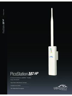
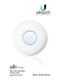
1 InstallerQuick Start GuideAccessoriesCarabiner CarabinerClip LoopThe U-Installer comes with a Carabiner for optional use. Insert the Carabiner through the Clip Loop and attach the Carabiner to a belt loop or utility belt as OverviewFront ViewWi-Fi LEDB attery LEDsPortsPoE OUT Supplies 24V passive PoE to the device being USB Type C port used for charging the internal Lights blue if the U-Installer has a Wi-Fi connection to your mobile Four blue LEDs indicate the internal battery s charge level: Full chargeLow charge** Recharge the battery by connecting a power source, such as a mobile battery pack, to the USB-C ViewButtonsRemovable RubberCasingButtonsReset ExtPowerResetReset Ext To reset the device connected to the U-Installer to factory defaults, press this button while the device is powered on.
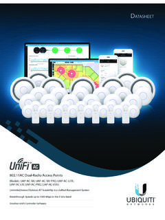
2 Hold the button for more than eight seconds until the LEDs on the device Press to power the U-Installer on or off. The Battery LEDs light when power is To reset the U-Installer to factory defaults, press and hold the Reset button while the U-Installer is powered on until the LEDs on the device a CPE DeviceUse a mobile device (default method) or a laptop to configure the CPE device at the point of installation via the U-Installer s Wi-Fi:1. Power on the U-Installer by pressing the Power button. The Battery LEDs light when the power is : If the battery level is low, connect a USB cable from a mobile power pack or USB charger to the USB-C port of the U-Installer . 2. Connect an Ethernet cable to the PoE OUT port on the U-Installer .
3 3. Connect the other end of the cable to the CPE have two options for configuration: the UNMS App and Web to the appropriate instructions:UNMS App - Default Method1. iOS devices only: Connect your mobile device s Wi-Fi to the U-Installer SSID named: ubi:<MAC Address> 2. Launch the UNMS app on your mobile device. Note: If the UNMS app is not yet installed on your mobile device, download it from App Store (iOS) or Google Play (Android). 3. The Connections screen (Mount Included)140 x 140 x 54 mm ( x x ") Weight (Mount Included)320 g ( oz)Operating Frequencyxxxx - xxxx MHzUSE EITHER THIS ROW OR THE FREQ. TABLE BELOW - DELETE WHICHEVER IS UNUSEDGain16 dBiNetworking Interface(1) 10/100/1000 Ethernet PortLEDsBattery Strength, PowerButtonsExternal Reset, Power, ResetEnclosureOutdoor UV Stabilized PlasticMax.
4 Power Consumption6 WPower Supply24V, Gigabit PoE Adapter (Included)Power MethodPassive PoE (Pairs 4, 5+; 7, 8 Return)Supported Voltage Rangexx to xxVDCO perating Temperature-40 to 80 C (-40 to 176 F)Operating Humidity5 to 95% NoncondensingSalt Fog TestIEC 68-2-11 (ASTM B117), Equivalent: MIL-STD-810 G Method TestIEC 68-2-6 Temperature Shock TestIEC 68-2-14UV TestIEC 68-2-5 at 40 C (104 F) Equivalent: ETS 300 019-1-4 Wind-Driven Rain TestETS 300 019-1-4 Equivalent: MIL-STD-810 G Method Protection 24kV Contact/AirShock and , FCC, IC4. Connect to the CPE device as follows:iOS: a. On the Connections screen, tap the CPE Tap Log in to automatically log into the :a. Tap , and then tap installer . b.
5 The app will automatically detect and connect to the U-Installer SSID named: ubi:<MAC Address>. c. On the Discover screen, tap the CPE device to automatically log into the Follow the on-screen instructions in the UNMS app to configure the connected Portal1. Connect your device s Wi-Fi to the U-Installer SSID named: ubi:<MAC Address>2. Open a web browser and go to: The login portal of the CPE device will appear. Log in using the appropriate username and Login Screen for CPE Device4. Configure the CPE device as the U-InstallerAfter you have configured the CPE device, remove the U-Installer :1. Disconnect the Ethernet cable from the Connect the Ethernet cable from a PoE adapter or switch to the U-InstallerWi-Fi GHzMax Transmit Power22 dBmMax Power ConsumptionU-InstallerU- installer with CPE3W15 WSafety Notices1.
6 Read, follow, and keep these Heed all Only use attachments/accessories specified by the : Do not use this product in a location that can be submerged by water. WARNING: Avoid using this product during an electrical storm. There may be a remote risk of electric shock from lightning. Electrical Safety Information1. Compliance is required with respect to voltage, frequency, and current requirements indicated on the manufacturer s label. Connection to a different power source than those specified may result in improper operation, damage to the equipment or pose a fire hazard if the limitations are not There are no operator serviceable parts inside this equipment. Service should be provided only by a qualified service Contact a qualified electrician or the manufacturer if there are questions about the installation prior to connecting the Protective earthing is provided by Listed AC adapter.
7 Building installation shall provide appropriate short-circuit backup Protective bonding must be installed in accordance with local national wiring rules and WarrantyUBIQUITI Networks , Inc ( Ubiquiti Networks ) warrants that the product(s) furnished hereunder (the Product(s) ) shall be free from defects in material and workmanship for a period of one (1) year from the date of shipment by Ubiquiti Networks under normal use and operation. Ubiquiti Networks sole and exclusive obligation and liability under the foregoing warranty shall be for Ubiquiti Networks , at its discretion, to repair or replace any Product that fails to conform to the above warranty during the above warranty period. The expense of removal and reinstallation of any Product is not included in this warranty.
8 The warranty period of any repaired or replaced Product shall not extend beyond its original term. Warranty ConditionsThe above warranty does not apply if the Product:(I) has been modified and/or altered, or an addition made thereto, except by Ubiquiti Networks , or Ubiquiti Networks authorized representatives, or as approved by Ubiquiti Networks in writing;(II) has been painted, rebranded or physically modified in any way;(III) has been damaged due to errors or defects in cabling;(IV) has been subjected to misuse, abuse, negligence, abnormal physical, electromagnetic or electrical stress, including lightning strikes, or accident;(V) has been damaged or impaired as a result of using third party firmware;(VI) has no original Ubiquiti MAC label, or is missing any other original Ubiquiti label(s).
9 Or(VII) has not been received by Ubiquiti within 30 days of issuance of the addition, the above warranty shall apply only if: the product has been properly installed and used at all times in accordance, and in all material respects, with the applicable Product documentation; all Ethernet cabling runs use CAT5 (or above), and for outdoor installations, shielded Ethernet cabling is used, and for indoor installations, indoor cabling requirements are followed.*640-00289-05*640-00289-05 ReturnsNo Products will be accepted for replacement or repair without obtaining a Return Materials Authorization (RMA) number from Ubiquiti Networks during the warranty period, and the Products being received at Ubiquiti Networks facility freight prepaid in accordance with the RMA process of Ubiquiti Networks .
10 Products returned without an RMA number will not be processed and will be returned freight collect or subject to disposal. Information on the RMA process and obtaining an RMA number can be found at: FOR ANY EXPRESS WARRANTIES PROVIDED HEREIN, Ubiquiti Networks , ITS AFFILIATES, AND ITS AND THEIR THIRD PARTY DATA, SERVICE, SOFTWARE AND HARDWARE PROVIDERS HEREBY DISCLAIM AND MAKE NO OTHER REPRESENTATION OR WARRANTY OF ANY KIND, EXPRESS, IMPLIED OR STATUTORY, INCLUDING, BUT NOT LIMITED TO, REPRESENTATIONS, GUARANTEES, OR WARRANTIES OF MERCHANTABILITY, ACCURACY, QUALITY OF SERVICE OR RESULTS, AVAILABILITY, SATISFACTORY QUALITY, LACK OF VIRUSES, QUIET ENJOYMENT, FITNESS FOR A PARTICULAR PURPOSE AND NON-INFRINGEMENT AND ANY WARRANTIES ARISING FROM ANY COURSE OF DEALING, USAGE OR TRADE PRACTICE IN CONNECTION WITH SUCH PRODUCTS AND SERVICES.