Transcription of 8254 PROGRAMMABLE INTERVAL TIMER - Stanford University
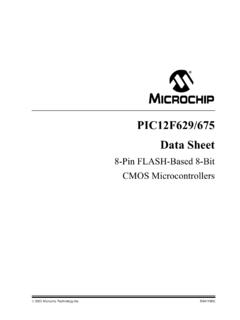
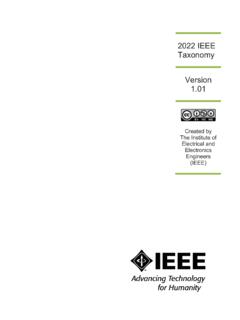
1 September 1993 Order Number: 231164-0058254 PROGRAMMABLE INTERVAL TIMERYC ompatible with All Intel and MostOther MicroprocessorsYHandles Inputs from DC to 10 MHz 8 MHz 8254 10 MHz 8254-2 YStatus Read-Back CommandYSix PROGRAMMABLE Counter ModesYThree Independent 16-Bit CountersYBinary or BCD CountingYSinglea5V SupplyYAvailable in EXPRESS Standard Temperature RangeThe Intel 8254 is a counter/ TIMER device designed to solve the common timing control problems in microcom-puter system design. It provides three independent 16-bit counters, each capable of handling clock inputs upto 10 MHz. All modes are software PROGRAMMABLE . The 8254 is a superset of the 8254 uses HMOS technology and comes in a 24-pin plastic or CERDIP 1 Figure 1. 8254 Block Diagram231164 2 Figure 2. Pin Configuration8254 Table 1. Pin DescriptionSymbolPinTypeName and D01 8I/ODATA:Bi-directional three state data bus lines, connected to systemdata 09 ICLOCK 0:Clock input of Counter 010 OOUTPUT 0:Output of Counter 011 IGATE 0: gate input of Counter :Power supply :a5V power supply CONTROL:This input is low during CPU write CONTROL:This input is low during CPU read SELECT:A low on this input enables the 8254 to respond toRDand WRsignals.
2 RDand WRare ignored ,A020 19 IADDRESS:Used to select one of the three Counters or the ControlWord Register for read or write operations. Normally connected tothe system address 001 Counter 110 Counter 211 Control Word RegisterCLK 218 ICLOCK 2:Clock input of Counter 217 OOUT 2:Output of Counter 216 IGATE 2: gate input of Counter 115 ICLOCK 1:Clock input of Counter 114 IGATE 1: gate input of Counter 113 OOUT 1:Output of Counter DESCRIPTIONG eneralThe 8254 is a PROGRAMMABLE INTERVAL TIMER /counterdesigned for use with Intel microcomputer is a general purpose, multi-timing element that canbe treated as an array of I/O ports in the 8254 solves one of the most common problemsin any microcomputer system, the generation of ac-curate time delays under software control. Instead ofsetting up timing loops in software, the programmerconfigures the 8254 to match his requirements andprograms one of the counters for the desired the desired delay, the 8254 will interrupt theCPU.
3 Software overhead is minimal and variablelength delays can easily be of the other counter/ TIMER functions commonto microcomputers which can be implemented withthe 8254 are:#Real time clock#Event-counter#Digital one-shot# PROGRAMMABLE rate generator#Square wave generator#Binary rate multiplier#Complex waveform generator#Complex motor controllerBlock DiagramDATA BUS BUFFERThis 3-state, bi-directional, 8-bit buffer is used to in-terface the 8254 to the system bus (see Figure 3).28254231164 3 Figure 3. Block Diagram Showing Data Bus Buffer and Read/Write Logic FunctionsREAD/WRITE LOGICThe Read/Write Logic accepts inputs from the sys-tem bus and generates control signals for the otherfunctional blocks of the 8254. A1and A0select oneof the three counters or the Control Word Registerto be read from/written into.
4 A low on the RDin-put tells the 8254 that the CPU is reading one of thecounters. A low on the WRinput tells the 8254that the CPU is writing either a Control Word or aninitial count. Both RDand WRare qualified by CS;RDand WRare ignored unless the 8254 has beenselected by holding WORD REGISTERThe Control Word Register (see Figure 4) is selectedby the Read/Write Logic when A1,A0e11. If theCPU then does a write operation to the 8254, thedata is stored in the Control Word Register and isinterpreted as a Control Word used to define theoperation of the Control Word Register can only be written to;status information is available with the 0, COUNTER 1, COUNTER 2 These three functional blocks are identical in opera-tion, so only a single Counter will be described. Theinternal block diagram of a single counter is shownin Figure Counters are fully independent.
5 Each Countermay operate in a different Control Word Register is shown in the figure; itis not part of the Counter itself, but its contents de-termine how the Counter status register, shown in Figure 5, whenlatched, contains the current contents of the ControlWord Register and status of the output and nullcount flag. (See detailed explanation of the Read-Back command.)The actual counter is labelled CE (for Counting Ele-ment ). It is a 16-bit presettable synchronous OLLare two 8-bit latches. OL stands for Output Latch ; the subscripts M and L stand for Most significant byte and Least significant byte 38254231164 4 Figure 4. Block Diagram Showing Control Word Register and Counter Functions231164 5 Figure 5. Internal Block Diagram of a Counter48254respectively. Both are normally referred to as oneunit and called just OL.
6 These latches normally fol-low the CE, but if a suitable Counter Latch Com-mand is sent to the 8254, the latches latch thepresent count until read by the CPU and then returnto following the CE. One latch at a time is enabledby the counter s Control Logic to drive the internalbus. This is how the 16-bit Counter communicatesover the 8-bit internal bus. Note that the CE itselfcannot be read; whenever you read the count, it isthe OL that is being , there are two 8-bit registers called CRMand CRL(for Count Register ). Both are normallyreferred to as one unit and called just CR. When anew count is written to the Counter, the count isstored in the CR and later transferred to the CE. TheControl Logic allows one register at a time to beloaded from the internal bus. Both bytes are trans-ferred to the CE simultaneously.
7 CRMand CRLarecleared when the Counter is programmed. In thisway, if the Counter has been programmed for onebyte counts (either most significant byte only or leastsignificant byte only) the other byte will be that the CE cannot be written into; whenever acount is written, it is written into the Control Logic is also shown in the n, gate n, and OUT n are all connected to theoutside world through the Control SYSTEM INTERFACEThe 8254 is a component of the Intel MicrocomputerSystems and interfaces in the same manner as allother peripherals of the family. It is treated by thesystem s software as an array of peripheral I/Oports; three are counters and the fourth is a controlregister for MODE , the select inputs A0,A1connect to the A0,A1address bus signals of the CPU. The CS can bederived directly from the address bus using a linearselect method.
8 Or it can be connected to the outputof a decoder, such as an Intel 8205 for larger DESCRIPTIONG eneralAfter power-up, the state of the 8254 is Mode, count value, and output of all Countersare each Counter operates is determined when it isprogrammed. Each Counter must be programmedbefore it can be used. Unused counters need not the 8254 Counters are programmed by writing a Control Wordand then an initial Control Words are written into the Control WordRegister, which is selected when A1,A0e11. TheControl Word itself specifies which Counter is 6 Figure 6. 8254 System Interface58254 Control Word FormatA1,A0e11 CSe0 RDe1 WRe0D7D6D5D4D3D2D1D0SC1 SC0 RW1 RW0 M2 M1 M0 BCDSC Select CounterSC1SC000 Select Counter 001 Select Counter 110 Select Counter 211 Read-Back Command(see Read Operations)RW Read/WriteRW1 RW00 0 Counter Latch Command (see ReadOperations)0 1 Read/Write least significant byte only1 0 Read/Write most significant byte only1 1 Read/Write least significant byte first,then most significant byteM ModeM2M1M0000 Mode 0001 Mode 1X10 Mode 2X11 Mode 3100 Mode 4101 Mode 5 BCD0 Binary Counter 16-bits1 Binary Coded Decimal (BCD) Counter(4 Decades)NOTE:Don t care bits (X) should be 0 to insure compatibility with future Intel 7.
9 Control Word FormatBy contrast, initial counts are written into the Coun-ters, not the Control Word Register. The A1,A0in-puts are used to select the Counter to be writteninto. The format of the initial count is determined bythe Control Word OperationsThe programming procedure for the 8254 is veryflexible. Only two conventions need to be remem-bered:1) For each Counter, the Control Word must be writ-ten before the initial count is ) The initial count must follow the count formatspecified in the Control Word (least significantbyte only, most significant byte only, or least sig-nificant byte and then most significant byte).Since the Control Word Register and the threeCounters have separate addresses (selected by theA1,A0inputs), and each Control Word specifies theCounter it applies to (SC0,SC1 bits), no special in-struction sequence is required.
10 Any programmingsequence that follows the conventions in Figure 7 new initial count may be written to a Counter atany time without affecting the Counter s pro-grammed Mode in any way. Counting will be affectedas described in the Mode definitions. The new countmust follow the programmed count a Counter is programmed to read/write two-bytecounts, the following precaution applies: A programmust not transfer control between writing the firstand second byte to another routine which also writesinto that same Counter. Otherwise, the Counter willbe loaded with an incorrect Word Counter 011 LSB of count Counter 000 MSB of count Counter 000 Control Word Counter 111 LSB of count Counter 101 MSB of count Counter 101 Control Word Counter 211 LSB of count Counter 210 MSB of count Counter 210A1A0 Control Word Counter 011 Control Word Counter 111 Control Word Counter 211 LSB of count Counter 210 LSB of count Counter 101 LSB of count Counter 000 MSB of count Counter 000 MSB of count Counter 101 MSB of count Counter 210A1A0 Control Word Counter 211 Control Word Counter 111 Control Word Counter 011 LSB of count Counter 210 MSB of count Counter 210 LSB of count Counter 101 MSB of count Counter 101 LSB of count Counter 000 MSB of count Counter 000A1A0 Control Word Counter 111 Control Word Counter 011 LSB of count Counter 101 Control Word