Transcription of PFC controller - NXP
1 TEA19162T/3 PFC controllerRev. 3 7 May 2018 Product data sheet 1 General descriptionThe TEA19162T and TEA19161T are combined controller (combo) ICs for resonanttopologies including PFC. They provide high efficiency at all power levels. Togetherwith the TEA1995T dual LLC resonant SR controller , a cost-effective resonant powersupply can be built. This power supply meets the efficiency regulations of Energy Star,the Department of Energy (DoE), the Eco-design Directive of the European Union, theEuropean Code of Conduct, and other TEA19162T is a Power Factor Correction (PFC) controller . The IC communicateswith the TEA19161T on start-up sequence and protections. It also enables a fast latchreset mechanism. To maximize the overall system efficiency, the TEA19161T allowssetting the TEA19161T PFC to burst mode at a low output power the TEA19161T and TEA19162T combo together with the TEA1995T secondarysynchronous rectifier controller , a highly efficient and reliable power supply can bedesigned with a minimum of external components.
2 The target output power is between90 W and 500 system provides a very low no-load input power (< 75 mW; total system including theTEA19161T/TEA19162T combo and theTEA1995T) and high efficiency from minimum tomaximum load. So, no additional low-power supply is SemiconductorsTEA19162T/3 PFC controllerTEA19162 TAll information provided in this document is subject to legal disclaimers. NXP 2019. All rights data sheetRev. 3 7 May 20182 / 302 Features and features Complete functionality as TEA19161T/TEA19162T combo Integrated X-capacitor discharge without additional external components Universal mains supply operation (70 V (AC) to 276 V (AC)) Integrated soft start and soft stop Accurate boost voltage features Valley/zero voltage switching for minimum switching losses Frequency limitation to reduce switching losses Reduced supply current (200 A) when in burst features Safe restart mode for system fault conditions Continuous mode protection with demagnetization detection Accurate OverVoltage Protection (OVP) Open-Loop Protection (OLP) Short-Circuit Protection (SCP) Internal and external IC OverTemperature Protection (OTP) Low and adjustable OverCurrent Protection (OCP)
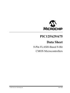
3 Trip level Adjustable brownin/brownout protection Supply UnderVoltage Protection (UVP)3 Applications Desktop and all-in-one PCs LCD television Notebook adapter Printers Gaming console power suppliesNXP SemiconductorsTEA19162T/3 PFC controllerTEA19162 TAll information provided in this document is subject to legal disclaimers. NXP 2019. All rights data sheetRev. 3 7 May 20183 / 304 Ordering informationTable 1. Ordering informationPackageType numberNameDescriptionVersionTEA19162T/3S O8plastic small outline package; 8 leads; body width mmSOT96-15 MarkingTable 2. Marking codesType numberMarking codeTEA19162T/3EA19162 NXP SemiconductorsTEA19162T/3 PFC controllerTEA19162 TAll information provided in this document is subject to legal disclaimers. NXP 2019. All rights data sheetRev.
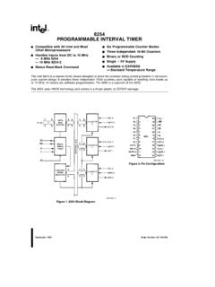
4 3 7 May 20184 / 306 Block diagramX-CAPDISCHARGECONTROL reset+ + AND VALLEY DETECTIONSUPPLYTIMER sTIMER 50 msUVPM ainsStartMainsStartXCapDisMAINSCURRENTTR ACKINGDELAY100 scurrentcomparatorTIMER118 msTIMER4msGATESENSINGSENSERESISTORSENSIN GDRIVERGatePfcTIMER sVALLEYDETECTIONZEROCURRENTSIGNALINTERNA LSUPPLIESSRdQSRdQMAINS SENSINGCONTROLOVP controlTEMPERATURESENSINGPFCOSCILLATORGa tePfcdemagExtOTPNTCM easureExt-OTPMAINSSENSING-90 mV+2 V+ VSNSAUXSUPICSNSMAINSaaa-017283200 A210 AGm amplifier5 A+ VOVB oostSoftStopsoft stop+ VOLP+2 VSNSBOOST100 AResetFastLatchBOOSTVOLTAGESENSINGON-TIM ECONTROLEndFastLatch+ V+ VProtActiveSoftStopNTCmeasure26 A26 A+13 VStartSUPICS tartMainsProtActiveSNSCURGATEPFCOCP+ +9 VUVPSUPIC+5 V Ana+5 V Dig+11 VPROTECTIONSCURRENTSENSINGGATECONTROLSTA RTUPCONTROLOTPX-CAPDISCHARGE mainscompensation+ + VenablePFC+ + V+ VPFCCOMPGND32 A+ +50mVSNSCURF igure 1.
5 Block diagramNXP SemiconductorsTEA19162T/3 PFC controllerTEA19162 TAll information provided in this document is subject to legal disclaimers. NXP 2019. All rights data sheetRev. 3 7 May 20185 / 307 Pinning 2. Pin descriptionTable 3. Pin descriptionSymbolPinDescriptionGATEPFC1g ate driver output for PFCGND2groundSNSCUR3programmable current sense input for PFCSUPIC4supply voltageSNSBOOST5sense input for PFC output voltageSNSMAINS6sense input for mains voltagePFCCOMP7frequency compensation pin for PFCSNSAUX8input from auxiliary winding for demagnetization timing and valleydetection for PFCNXP SemiconductorsTEA19162T/3 PFC controllerTEA19162 TAll information provided in this document is subject to legal disclaimers. NXP 2019. All rights data sheetRev. 3 7 May 20186 / 308 Functional controlThe TEA19162T is a controller for a power factor correction circuit.
6 Figure 3 shows atypical converterPFCSNSAUXGATEPFCSNSMAINSSNSCURS UPICV mains-LVmains-NRmainsGNDSNSBOOSTV boostCboostPFCCOMPRauxRSNSCURR senseRSNSBOOSTM1 CSUPICF igure 3. TEA19162T typical voltage and start-upWhen using the TEA19162T (PFC) together with the TEA19161T (LLC), connect theSUPIC pin of the TEA19162T to the SUPIC pin of the TEA19161T. The LLC controllerthen supplies the PFC either via the high-voltage supply pin of the TEA19161T (SUPHV)or via the primary auxiliary enable the PFC, the SUPIC voltage must exceed the Vstart(SUPIC) level (13 V typical).Although the Vstart(SUPIC) level of the LLC is higher than the Vstart(SUPIC) level of the PFC,the system ensures that both converters (PFC and LLC) start up at the same , the LLC initially pulls down the SNSBOOST pin, disabling the PFC until theSUPIC voltage reaches the Vstart(SUPIC) level of the both conditions are met and the SNSMAINS is above the brownin level, the PFCstarts up via an internal soft start (see Figure 4).
7 NXP SemiconductorsTEA19162T/3 PFC controllerTEA19162 TAll information provided in this document is subject to legal disclaimers. NXP 2019. All rights data sheetRev. 3 7 May 20187 / 30t4t3t2t1aaa-020197td(start)VSNSBOOSTVS UPICLLCPFC VboostVstart(SNSBOOST) (SNSBOOST) VVpu(rst)SNSBOOST VVscp(stop) VVuvp(SUPIC) 9 VVstart(SUPIC) VVbrowninmains voltageVrst(SUPIC) (SUPIC) (hys) (SUPIC) mode of operationt6t5 Figure 4. Start-up of the PFC and LLCThe exact start-up sequence of the PFC depends on the availability of start-up conditions(brownin level, Vstart(SUPIC) of the PFC, and Ien(PFC)).Before t1, the SUPIC voltage is below the UVP level of the PFC and LLC. When the LLCreaches a minimum supply voltage level (t1), the LLC pulls down the SNSBOOST pin todisable the t2, the SUPIC voltage reaches the start level of the PFC converter.
8 However, asthe LLC pulls low the SNSBOOST to below the PFC short protection level, the PFC isstill off. When the mains voltage exceeds the brownin level, the PFC resets its latchedprotection by pulling VSNSBOOST to the Vpu(rst)SNSBOOST level (t3). However, the LLCreturns it to the protection mode. When at t4 the SUPIC voltage reaches the start levelof the LLC, the SNSBOOST is released. The SNSBOOST voltage increases becauseof the resistive divider which is connected to the PFC bus voltage. To ensure that thisvoltage is representative of the Vboost voltage before the system actually starts to switch,an additional delay (td(start); ms) is active before the PFC starts switching (t5).Another important condition for the PFC start is a precharge of the compensation circuitryconnected to the PFCCOMP pin.
9 This condition is met when the current out of thePFCCOMP pin < |Ien(PFCCOMP)|.NXP SemiconductorsTEA19162T/3 PFC controllerTEA19162 TAll information provided in this document is subject to legal disclaimers. NXP 2019. All rights data sheetRev. 3 7 May 20188 / 30 When at t6 the SNSBOOST voltage reaches the start level of the LLC (Vstart(SNSBOOST)),the LLC converter starts to VSUPIC < Vuvp(SUPIC), the PFC controller stops switching 4 gives an overview of the available 4. Protections overviewProtectionDescriptionActionLLC[1]UVP-SUPIC undervoltage protection SUPICPFC = off; restart whenVSUPIC > Vstart(SUPIC); SNSBOOST pulled low, disabling the overtemperature protectionlatched; SNSBOOST pulled low,disabling the overtemperature protectionlatched; SNSBOOST pulled low,disabling the protection mainsPFC = off; restart whenISNSMAINS > Ibi[2]-Section protection boost voltagefollowed by a soft stopPFC = off via soft stop; restart whenVSNSBOOST < Vovp(start)-Section protection boost voltagePFC = off; restart whenVSNSBOOST < Vovp(SNSBOOST)-Section protectionPFC = off; restart whenVSNSBOOST > Vscp(start)-Section protectionPFC = off.
10 Restart whenVSNSBOOST > Vscp(start)-Section protectionPFC MOSFET switched off,continue operation-Section [1]Some protections also disable the LLC (see Section ).[2]At start-up, the PFC disables the LLC converter until the mains voltage exceeds the brownin OverTemperature Protection (OTP)An accurate internal temperature protection is provided in the circuit. When the junctiontemperature exceeds the thermal shutdown temperature (Tpl(IC)), the IC stops internal overtemperature protection is a latched protection. It also disables the LLCconverter by pulling down the SNSBOOST SemiconductorsTEA19162T/3 PFC controllerTEA19162 TAll information provided in this document is subject to legal disclaimers. NXP 2019. All rights data sheetRev. 3 7 May 20189 / and external overtemperature protectionOn the TEA19162T, the mains measurement and external temperature are combined atthe SNSMAINS pin (see Figure 5).