Transcription of A Channel Otpt an Controller - Maxim Integrated
1 General DescriptionThe MAX31790 controls the speeds of up to six fans using six independent PWM outputs. The desired fan speeds (or PWM duty cycles) are written through the I2C interface. The outputs drive 4-wire fans directly, or can be used to modulate the fan s power terminals using an external pass inputs monitor fan tachometer logic outputs for precise (Q1%) monitoring and control of fan RPM as well as detection of fan failure. Six pins are dedicated tachometer inputs.
2 Any of the six PWM outputs can also be configured to serve as tachometer PWM_START inputs select the PWM output status at startup to ensure appropriate fan drive when power is first ensure low acoustic impact of fan control, all changes in PWM duty cycle take place at a controlled, program-mable MAX31790 s to supply voltage range and I2C-compatible interface make it ideal for fan control in a wide range of cooling applications. The MAX31790 is available in a 28-pin TQFN package and operates over the -40NC to +125NC temperature and Features Provides Precise Fan Control and Monitoring for Large Fan Count Applications Controls Up to Six Independent Fans with PWM Drive Up to 12 Tachometer Inputs Controlled Duty Cycle Rate-of-Change for Best Acoustics Improves System Reliability Versatile Startup Configurations Provide Reliable Fan Control at Power-up without Having to Wait for System C Direction
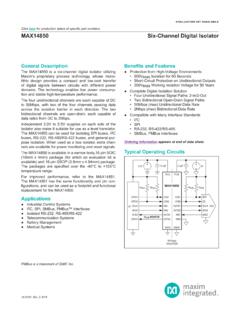
3 I2C Bus Interface with Timeout and WatchdogApplications Servers Networking Telecom19-6540; Rev 3; 5/20 Ordering Information appears at end of data TO (OPTIONAL) F12pF12pFPWMOUT2 TACH2 PWMOUT3 TACH3 PWM OUTPUTDRIVER,TACH MONITORI2C INTERFACE,REGISTERS,ANDCONTROL LOGICPWMOUT4 TACH4 PWMOUT5 TACH5 PWMOUT1 SDAVCCXTAL2 XTAL1 TACH1 SCLFAN_FAILHOSTINTERFACESETPOWER-UPVALUE SCLKOUTFULL_SPEEDPWMOUT6 TACH6 GND6 CHANNELSPWM_START1 PWM_START0 FREQ_STARTSPIN_STARTWD_STARTADD1 ADD0 Typical Operating CircuitMAX317906- Channel PWM-Output Fan RPM ControllerEVALUATION KIT AVAILABLEV oltage Range on VCC, SDA, SCL, ADD0, ADD1, FAN_FAIL, PWMOUTn Relative to GND.
4 To + Range on TACHn, WD_START, SPIN_START, FREQ_START, CLKOUT, FULL_SPEED, PWM_STARTn Relative to GND .. to VCC + (not to exceed + )Input Current at Any Pin ..+5mAPackage Input Current ..+20mAContinuous Power Dissipation (TA = +70NC) TDFN (derate mW/NC above +70NC) .. Temperature Range ..-40NC to +125 NCStorage Temperature Range ..-65NC to +150 NCJunction Temperature ..+150 NCESD Protection (All Pins, HBM) (Note 1) ..Q2000 VLead Temperature (soldering, 10s) ..+300 NCSoldering Temperature (reflow).
5 +260NC(TA = -40 C to +125 C, unless otherwise noted.) (Notes 2, 3)(TA = -40 C to +125 C, typical values are VCC = , TA = +25 C, unless otherwise noted.) (Notes 2, 3)PARAMETERSYMBOLCONDITIONSMINTYPMAXUNIT SO perating Supply High VoltageVIHVCC x Low VoltageVILVCC x Supply Current (Note 4) < VCC < < VCC < ThresholdVPOR2 VWatchdog Timer AccuracyfTOSC = (Note 5) + Low Voltage (SDA, FAN_FAIL, PWMOUTn, CLKOUT)IOL = High Voltage (CLKOUT)IOH = 1mA, VCC = Input Leakage IL(Note 6)-1+1 FAInput CapacitanceAll digital inputs5pFAbsolute Maximum RatingsStresses beyond those listed under Absolute Maximum Ratings may cause permanent damage to the device.
6 These are stress ratings only, and functional operation of the device at these or any other conditions beyond those indicated in the operational sections of the specifications is not implied. Exposure to absolute maximum rating conditions for extended periods may affect device 1: Human Body Model, 100pF discharged through a Operating ConditionsElectrical Integrated 2 MAX317906- Channel PWM-Output Fan RPM Controller (TA = -40 C to +125 C, typical values are VCC = , TA = +25 C, unless otherwise noted.)
7 (Note 3)(VCC = + to + , TA = -40 C to +125 C, timing referenced to VIL(MAX) and VIH(MIN), unless otherwise noted.) (Notes 3, 8) (Figure 1)PARAMETERSYMBOLCONDITIONSMINTYPMAXUNIT SS erial Clock FrequencyfSCLDC400kHzBus Free Time Between STOP and START Condition Hold Condition Setup TimetSU:STO90% of SCL to 10% of SDA600nsClock Low High Condition Setup TimetSU:STA90% of SCL to 90% of SDA100nsData Setup TimetSU:DAT10% of SDA to 10% of SCL100nsData In Hold Time tHD:DAT10% of SCL to 10% of SDA (Note 9) Receive SCL/SDA Rise Time tR(Note 10)300nsMinimum Receive SCL/SDA Rise Time tR(Note 10)20 + x CBnsPARAMETERSYMBOLCONDITIONSMINTYPMAXUN ITSPWM Resolution99 BitsPWM Frequency Accuracy-6+6%TACH Count Resolution1111 BitsTACH Count Oscillator and CLKOUT ClockfTOSC(Note 7) Count Oscillator and CLKOUT Accuracy (Note 7)fERR:TOSCU sing internal oscillator: TA = +25 C, VCC = + internal oscillator: 0 C < TA < +70 C, < VCC < + internal oscillator.
8 -40 C < TA < +125 C, < VCC < + internal oscillator: -40 C < TA < +125 C, < VCC < + external + Minimum Input Pulse WidthtTACHMINP ulse width must be greater than this value to be detected2575 FsFan Control CharacteristicsI2C AC Electrical Integrated 3 MAX317906- Channel PWM-Output Fan RPM Controller (VCC = + to + , TA = -40 C to +125 C, timing referenced to VIL(MAX) and VIH(MIN), unless otherwise noted.) (Notes 3, 8) (Figure 1)(Notes 3)Note 2: All voltages referenced to ground.
9 Currents entering the IC are specified as 3: Limits are 100% production tested at TA = +25 C and/or TA = +85 C. Limits over the operating temperature range and rel-evant supply voltage range are guaranteed by design and characterization. Typical values are not 4: SDA = SCL = VCC, PWM active with PWM_FREQUENCY = 5: The watchdog timer is derived from fTOSC and the watchdog timer accuracy specifications do not include the oscillator s associated error 6: Applies to pins SDA, SCL, PWM_STARTn, WD_START, FREQ_START, SPIN_START, ADDn, TACHn, PWMOUTn, 7: fTOSC is used to measure fan speed by counting the number of 8192Hz (fTOSC/4) clock cycles that take place during a selectable number of tachometer periods.
10 For internal oscillator only, typical frequency shift due to aging is within Aging stressing includes level 1 moisture reflow preconditioning (24hr +125 C bake, 168hr +85 C/85%RH moisture soak, and three solder reflow passes +260 C +0 C/-5 C peak) followed by 192hr (max) VCC 8: All timing specifications are guaranteed by 9: A master device must provide a hold time of at least 300ns for the SDA signal to bridge the undefined region of SCL s falling 10: CB total capacitance of one bus line in 11: Holding the SDA line low for a time greater than tTIMEOUT causes the device to reset SDA to the idle state of the serial bus communication (SDA set high).
