Transcription of A Digital multiple beam forming for phased array …
1 IOSR Journal of VLSI and Signal Processing (IOSR-JVSP) Volume 4, Issue 1, Ver. I (Jan. 2014), PP 22-28 e-ISSN: 2319 4200, p-ISSN No. : 2319 4197 22 | Page A Digital multiple beam forming for phased array RADARs with parallel array processing Gaikwad(1), Mr. Radha Krishna AN(2) Faculty of Electronics & Communications Engineering. Annamacharya institute of Technology & Science,Hyderabad(1) Brilliant Group of Technical Institutions, Hyderabad(2). Abstract: phased array radar is very important in modern radar development, and multiple Digital beams forming technology is the most significant technology in phased array radar. beam forming is a signal processing technique used in antenna arrays for directional signal transmission or reception. Digital multiple beam forming on each antenna element about large phased array radar is impossible in processor based Digital processing units, because it needs simultaneous processing many A/D channels.
2 In this project we resolve this problem by using a multi array based beam forming technique with multiplexed signal processing unit on FPGA. The conventional technique of completely duplicated hardware and also dynamic reconfiguration does not yield the real time parallel beam processing. The proposed technique employs multiplexed signal processing unit which is time shared for various beam formers. This technique provides simultaneous beams without any compromise on functionality. I. Introduction In antenna theory, a phased array is an array of antennas in which the relative phases of the respective signals feeding the antennas are varied in such a way that the effective radiation pattern of the array is reinforced in a desired direction and suppressed in undesired directions. An antenna array is a group of multiple active antennas coupled to a common source or load to produce a directive radiation pattern.
3 Usually, the spatial relationship of the individual antennas also contributes to the directivity of the antenna array . Use of the term "active antennas" is intended to describe elements whose energy output is modified due to the presence of a source of energy in the element (other than the mere signal energy which passes through the circuit) or an element in which the energy output from a source of energy is controlled by the signal input. One common application of this is with a standard multiband television antenna , which has multiple elements coupled together. Digital multiple beam forming on each antenna element about large phased array radar is impossible in processor based Digital processing units, because it needs simultaneous processing many A/D channels. In this project we resolve this problem by using a multi array based beam forming technique with multiplexed signal processing unit on FPGA. The conventional technique of completely duplicated hardware and also dynamic reconfiguration does not yield the real time parallel beam processing.
4 The proposed technique employs multiplexed signal processing unit which is time shared for various beam formers. This technique provides simultaneous beams without any compromise on functionality. II. phased array antenna Electronically-steered phased array radar is an array of antennas in which the relative phases of the respective signals feeding the antennas are varied in such a way that the effective radiation pattern of the array is reinforced in a desired direction and suppressed in undesired directions. phased array transmission was originally developed in 1905 by Nobel Laureate Karl Ferdinand Braun who demonstrated enhanced transmission of radio waves in one direction. During World War II, Nobel Laureate Luis Alvarez used phased array transmission in a rapidly-steer able radar system for "ground-controlled approach", a system to aid in the landing of aero planes in Britain.
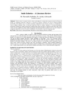
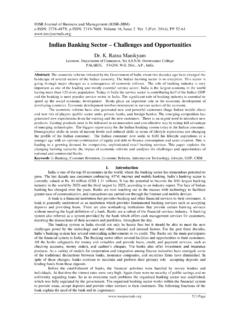
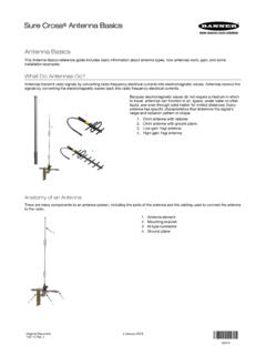
5 At the same time GEMA in Germany built the PESA Mammut. The design is also used in radar, and is generalized in inter-ferometric radio antennas. In 2007 DARPA researchers announced a 16 element phased array integrated with all necessary circuits to send at 30 50 GHz on a single silicon chip for military purposes. These antenna arrays completely consist of singles radiating elements and each of it gets an own phase shifter. The elements are ordered in a matrix array . The planer arrangement of all elements forms the complete phased array antenna . One of the advantages is the beam forming in two planes are Digital beam forming is possible. A Digital multiple beam forming for phased array RADARs with parallel array processing 23 | Page Fig : Electronic phased array beam formation III. Hardware Specifications 1 RF Translator Radio frequency (RF) is a rate of oscillation in the range of about 3 kHz to 300 GHz, which corresponds to the frequency of radio waves, and the alternating currents which carry radio signals.
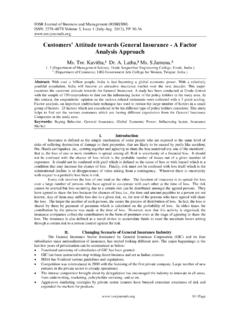
6 RF usually refers to electrical rather than mechanical oscillations, although mechanical RF systems do exist. In order to receive radio signals an antenna must be used. However, since the antenna will pick up thousands of radio signals at a time, a radio tuner is necessary to tune in to a particular frequency (or frequency range).This is typically done via a resonator in its simplest form, a circuit with a capacitor and an inductor forming a tuned circuit. Fig Digital beam forming The circuit amplifies oscillations within a particular frequency band, while reducing oscillations at other frequencies outside the band. III. Digital Down-Counter The principle of Digital Down-Counter which is taking the input from RF Translator that is given to the input of Fast ADC.
7 The output of Fast ADC block which is given to the DDC block. The DDC ( Digital Down-Counter) consists of NCO (Numerically Controlled Oscillator), Multiplier, low pass filter and Decimator. A Digital multiple beam forming for phased array RADARs with parallel array processing 24 | Page NCO (Oscillator) IV. Oscillator (NCO) The NCO main purpose is to generation the carrier signals (cosine).The main advantage is ROM based techniques will be used for area optimization. phase accumulator The output of phase accumulator when the phase increment value is 0000001000000000. It can be observed that the resulting phase value after each clock pulse is four added to the previous phase value. In the following figure initial phase is 0 and further with clock pulses resulting in 4, 8, 12, and 16.
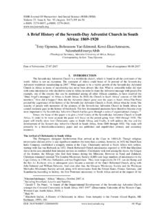
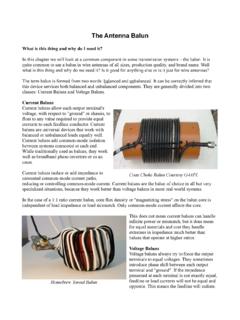
8 The output of phase accumulator is added with multiplier output. That output is given to NCO block. All the blocks are connected with common clock and reset signals. The delta phase value decides the phase increment for each clock pulse. Hence decides the resulting signal frequency. The Frequency modulating instantaneous value is added to the delta phase value which causes instantaneous change in frequency. Due to the Digital nature of the modulator only at each clock tick the modulating signal value shall affect the resulting frequency. If the modulating signal is analog then an Analog Digital converter must be used to digitize the modulating signal which can be used in NCO. 4 Low Pass Filter A low-pass filter is an electronic filter that passes low-frequency signals but attenuates (reduces the amplitude of) signals with frequencies higher than the cutoff frequency. The actual amount of attenuation for each frequency varies from filter to filter.
9 It is sometimes called a high-cut filter, or treble cut filter when used in audio applications. A low-pass filter is the opposite of a high-pass filter. A band-pass filter is a combination of a low-pass and a high-pass. A Digital multiple beam forming for phased array RADARs with parallel array processing 25 | Page Fig : Low Pass Filter V. Decimator (Filtering & Decimation) There are two main classes of DDC wideband and narrowband, differentiated by their decimation ratios. As a rough guide, if the decimation ratio is less than 32 consider the DDC wideband; if 32 or more, the DDC is filtering we will perform is different for narrowband or wideband, so is tackled separately. However, the decimators can be treated identically for wideband or narrowband systems.
10 VI. Designing the Filters There can be several tools by which the filter coefficients can be finalized for implementing the required FIR filters. In this project the MATLAB s filter design analysis tool (FDA) will be used for designing. An FIR filter is one whose impulse response is of finite duration. In this filter, the current output (yn) is calculated solely from the current and previous input values (xn, xn-1, ). This type of filter is also said to be non-recursive. The difference equation, which defines how the input signal is related to the output signal Where P is the filter order, x (n) is the input signal, y (n) is the output signal and bi are the filter coefficients. The previous equation can also be expressed as Fig Finite Impulse Response Digital Filters The transfer function allows us to judge whether or not a system is BIBO stable.