Transcription of A Technical Tutorial on the IEEE 802.11 Protocol
1 Copyright BreezeCOM 1997A Technical Tutorial on the IEEE ProtocolBy Pablo BrennerDirector of EngineeringA Technical Tutorial on the IEEE Standard18 July, 1996 BreezeCom copyright BreezeCOM 1997 Page 2 IntroductionThe purpose of this document is to give Technical readers a basic overview of the new Standard, insuch a way that they will be able to understand the basic concepts, the principle of operations, and some ofthe reasons behind some of the features and/or components of the the document does not cover all the Standard, and does not provide enough information for thereader to implement an compliant device (for this purpose the reader should read the Standarditself which is a several hundred pages document).This version of the document addresses mainly Functional and MAC aspects, a detailed description of thePHY layer will be provided in a following version of the document is actualized to Draft of the Technical Tutorial on the IEEE Standard18 July, 1996 BreezeCom copyright BreezeCOM 1997 Page 3 IEEE ArchitectureArchitecture ComponentsAn LAN is based on a cellular architecture where the system is subdivided into cells, where eachcell (called Basic Service Set or BSS, in the nomenclature) is controlled by a Base Station (calledAccess Point, or in short AP).
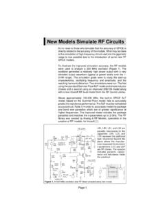
2 Even though that a wireless LAN may be formed by a single cell, with a single Access Point, (and as willbe described later, it can also work without an Access Point), most installations will be formed by severalcells, where the Access Points are connected through some kind of backbone (called Distribution Systemor DS), typically Ethernet, and in some cases wireless whole interconnected Wireless LAN including the different cells, their respective Access Points andthe Distribution System, is seen to the upper layers of the OSI model, as a single 802 network, and iscalled in the Standard as Extended Service Set (ESS).The following picture shows a typical LAN, with the components described previously:Distribution SystemDistribution SystemAPAPBSSBSSESSThe standard also defines the concept of a Portal, a Portal is a device that interconnects between and another 802 LAN.
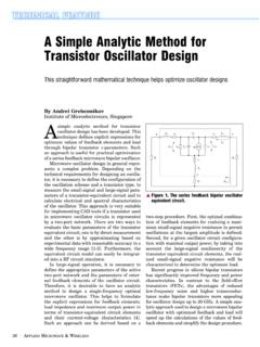
3 This concept is an abstract description of part of the functionality of a translation bridge .A Technical Tutorial on the IEEE Standard18 July, 1996 BreezeCom copyright BreezeCOM 1997 Page 4 Even though the standard does not necessarily request so, typical installations will have the AP and thePortal on a single physical entity, and this is the case with BreezeCom s AP which provides Technical Tutorial on the IEEE Standard18 July, 1996 BreezeCom copyright BreezeCOM 1997 Page 5 IEEE Layers DescriptionAs any Protocol , the Protocol covers the MAC and Physical Layer, the Standard currentlydefines a single MAC which interacts with three PHYs (all of them running at 1 and 2 Mbit/s) : Frequency Hopping Spread Spectrum in the GHz Band Direct Sequence Spread Spectrum in the GHz Band, and MACFHDSIRPHY LayerBeyond the standard functionality usually performed by MAC Layers, the MAC performs otherfunctions that are typically related to upper layer protocols, such as Fragmentation, Packet Retransmitions,and MAC LayerThe MAC Layer defines two different access methods, the Distributed Coordination Function and thePoint Coordination Function:The Basic Access Method: CSMA/CAThe basic access mechanism, called Distributed Coordination Function, is basically a Carrier SenseMultiple Access with Collision Avoidance mechanism (usually known as CSMA/CA).
4 CSMA protocolsare well known in the industry, where the most popular is the Ethernet, which is a CSMA/CD Protocol (CD standing for Collision Detection).A CSMA Protocol works as follows: A station desiring to transmit senses the medium, if the medium isbusy ( some other station is transmitting) then the station will defer its transmission to a later time, ifthe medium is sensed free then the station is allowed to kind of protocols are very effective when the medium is not heavily loaded, since it allows stationsto transmit with minimum delay, but there is always a chance of stations transmitting at the same time(collision), caused by the fact that the stations sensed the medium free and decided to transmit at Technical Tutorial on the IEEE Standard18 July, 1996 BreezeCom copyright BreezeCOM 1997 Page 6 These collision situations must be identified, so the MAC layer can retransmit the packet by itself and notby upper layers, which would cause significant delay.
5 In the Ethernet case this collision is recognized bythe transmitting stations which go to a retransmission phase based on an exponential random these Collision Detection mechanisms are a good idea on a wired LAN, they cannot be used on aWireless LAN environment, because of two main reasons:1. Implementing a Collision Detection Mechanism would require the implementation of a Full Duplexradio, capable of transmitting and receiving at once, an approach that would increase the On a Wireless environment we cannot assume that all stations hear each other (which is the basicassumption of the Collision Detection scheme), and the fact that a station willing to transmit andsenses the medium free, doesn t necessarily mean that the medium is free around the receiver order to overcome these problems, the uses a Collision Avoidance mechanism together with aPositive Acknowledge scheme, as follows:A station willing to transmit senses the medium, if the medium is busy then it defers.
6 If the medium isfree for a specified time (called DIFS, Distributed Inter Frame Space, in the standard) then the station isallowed to transmit, the receiving station will check the CRC of the received packet and send anacknowledgment packet (ACK). Receipt of the acknowledgment will indicate the transmitter that nocollision occurred. If the sender does not receive the acknowledgment then it will retransmit the fragmentuntil it gets acknowledged or thrown away after a given number of Carrier SenseIn order to reduce the probability of two stations colliding because they cannot hear each other, thestandard defines a Virtual Carrier Sense mechanism:A station willing to transmit a packet will first transmit a short control packet called RTS (Request ToSend), which will include the source, destination, and the duration of the following transaction ( thepacket and the respective ACK), the destination station will respond (if the medium is free) with aresponse control Packet called CTS (Clear to Send), which will include the same duration stations receiving either the RTS and/or the CTS, will set their Virtual Carrier Sense indicator(called NAV, for Network Allocation Vector)
7 , for the given duration, and will use this informationtogether with the Physical Carrier Sense when sensing the mechanism reduces the probability of a collision on the receiver area by a station that is hidden from the transmitter, to the short duration of the RTS transmission, because the station will hear the CTSand reserve the medium as busy until the end of the transaction. The duration information on the RTSalso protects the transmitter area from collisions during the ACK (by stations that are out of range fromthe acknowledging station).It should also be noted that because of the fact that the RTS and CTS are short frames, it also reduces theoverhead of collisions, since these are recognized faster than it would be recognized if the whole packetwas to be transmitted, (this is true if the packet is significantly bigger than the RTS, so the standardA Technical Tutorial on the IEEE Standard18 July, 1996 BreezeCom copyright BreezeCOM 1997 Page 7allows for short packets to be transmitted without the RTS/CTS transaction, and this is controlled perstation by a parameter called RTST hreshold).
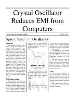
8 The following diagrams show a transaction between two stations A and B, and the NAV setting of theirneighbors:The NAV State is combined with the physical carrier sense to indicate the busy state of the Level AcknowledgmentsAs mentioned earlier in this document, the MAC layer performs the Collision Detection by expecting thereception of an acknowledge to any transmitted fragment (exception to these are packets that have morethan one destination, such as Multicasts, which are not acknowledged).Fragmentation and ReassemblyTypical LAN protocols use packets of several hundreds of bytes ( Ethernet longest packet could be upto 1518 bytes long), on a Wireless LAN environment there are some reasons why it would be preferable touse smaller packets: Because of the higher Bit Error Rate of a radio link , the probability of a packet to get corruptedincreases with the packet size.
9 In case of packet corruption (either because of collision or noise), the smallest the packet the lessoverhead it causes to retransmit it. On a Frequency Hopping system, the medium is interrupted periodically for hopping (in our caseevery 20 milliseconds), so the smaller the packet, the smaller the chance that the transmission will bepostponed to after the dwell Technical Tutorial on the IEEE Standard18 July, 1996 BreezeCom copyright BreezeCOM 1997 Page 8On the other hand, it doesn t make sense to introduce a new LAN Protocol that cannot deal with packetsof 1518 bytes which are used on Ethernet, so the committee decided to solve the problem by adding asimple fragmentation/reassembly mechanism at the MAC mechanism is a simple Send-and-Wait algorithm, where the transmitting station is not allowed totransmit a new fragment until one of the following happens:1.
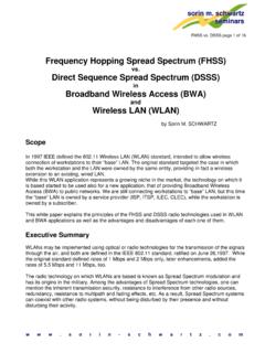
10 Receives an ACK for the said fragment, or2. Decides that the fragment was retransmitted too many times and drops the whole frameIt should be noted that the standard does allow the station to transmit to a different address betweenretransmissions of a given fragment, this is particularly useful when an AP has several outstandingpackets to different destinations and one of them does not following diagram shows a frame (MSDU) being divided to several fragments (MPDUs):MSDUMACHDRF rame BodyCRCMACHDRF rame BodyCRCMACHDRF rame BodyCRCMACHDRF rame BodyCRCF ragment 0 Fragment 1 Fragment 2 Fragment 3 Inter Frame SpacesThe Standard defines 4 types of Inter Frame Spaces, which are use to provide different priorities: SIFS - Which stands for Short Inter Frame Space, is used to separate transmissions belonging to asingle dialog ( Fragment-Ack), and is the minimum Inter Frame Space, and there is always atmost one single station to transmit at this given time, hence having priority over all other value is a fixed value per PHY and is calculated in such a way that the transmitting station willbe able to switch back to receive mode and be capable of decoding the incomming packet, on FH PHY this value is set to 28 microseconds PIFS - Point Cooordination IFS, is used by the Access Point (or Point Coordinator, as called in thiscase), to gain access to the medium before any other value is SIFS plus a Slot Time (defined in the following paragraph), 78 microseconds.