Transcription of A5000GEC ZERO SPEED SWITCH - Process Control …
1 PCSPROCESS Control SYSTEMSTMTMA5000 GECZERO SPEED SWITCHI ntroductionThe MAXIGARD A5000 GEC is a zero SPEED SWITCH designed to monitor the starting andstopping of critical rotating shafts. Principle of OperationThe A5000 Series SPEED switches have a non contact sensor and is supplied with amagnetic target. The sensor signal is not impaired by the build up of dust or any otherforeign material on the magnetic target or sensor. This SWITCH is designed to detect zerospeed (speeds less than 1 RPM) of the monitored shaft. The A5000 GEC has two relay contacts. The relay is energized as soon as one magnetpasses in front of the sensor and remains energized until the monitored shaft SPEED dropsbelow 1 RPM for more than approximately seconds. The relay re-energizes as soon asthe monitored shaft starts to rotate. The SWITCH is designed fail safe and in the event of apower failure, loss of signal, component failure etc.
2 The relay will A5000 GEC MOTION SWITCH INCLUDES:z4 MAGNET DISC (OTHER OPTIONAL TARGETS AVAILABLE)zSELF CONTAINED SWITCH HOUSING INCORPORATING SENSOR, CIRCUIT AND RELAYzMOUNTING BRACKET WITH MOUNTING SADDLEA208-05, Page 1327 LAKE HAZELTINE DRIVE, CHASKA, MN 55318800-328-0738952-361-3026 Process Control SYSTEMS, INC.(Fax) 952-368-4129 PCSPROCESS Control SYSTEMSTMCALL TOLL : 1 - end of the shaft to be monitored should be square to prevent excessive discwobble. drill and tap the shaft end. (Suggested #21 drill and #10-32NF tap). Bolt themagnet disc to the end of the shaft. Use Loc-tite to keep the bolt and disc tight onthe shaft.(see figure 1A, page 3). Wrap (optional) the two halves of the magnet wrap by loosening the cap screws holdingthe two halves both halves of the magnet wrap around the shaft. Re-insert and tighten thecap screws making sure the wrap is square to the shaft.
3 (see figure 1B, page 3). the zero SPEED the SWITCH so the sensor is centered directly in front of the magnets in the discor optional wrap.(see figure 1A & 1B, page 3). gap setting between the sensor and magnet disc should be approximately1/8 - 3/4 .NOTET here will be a slight gap between the two halves after tightening. Thisgap will not affect the generated , Page 2 PCSPROCESS Control SYSTEMSTMCALL TOLL : METHOD1/8" to 3/4" GAP1 5/8"SHAFTMAGNETSTANDARD MAGNET DISCF igure 1 AOPTIONAL MAGNET WRAPMAGNET1/8" to 3/4" GAPF igure 1 BMAGNET DISCA5000A5000 NFMAGNET WRAPMOUNTING BRACKET1/4"3/16"4"7/8"2 3/8"5 9/16"4 11/16"3 9/16"2"1" NPT2 3/4"1 1/16"5/16"1 5/8"1"1/8"2 7/8"2 1/16"3/8" DIA1/2"7/8"1 1/2"D+3"D"3 11/16"1 7/8"4 3/4"SENSOR1" NPT15/16"3 13/16"4 9/16"2"A5000 GEC1" HUB1 3/4"3 1/4"1 5/8"5 7/8"4 5/8"Figure 2 DIMENSIONAL DATAA208-05, Page 3 PCSPROCESS Control SYSTEMSTMCALL TOLL : zero SPEED SWITCH A5000 GEC zero SPEED SWITCH housing is UL/CSA listed and certified forClass I, Div.
4 1 & 2, Group D. Class II, Div. 1 & 2, Group E, F, & G. Class III.(see figure 2, page 3)SECTION 2 - FIELD the A5000 GEC zero SPEED connections and relay connections to the A5000 GEC zero SPEED Switchare shown on figure 3, page 4. Also, figure 4 & 5, page 5 & 6 show typical wiringdiagrams. 120 VAC power to the RED wire and neutral to the WHITE wire. Connectthe equipment safety ground to the GREEN wire on the A5000 GEC. (see figure 3, page 4). relay connections to YELLOW, BROWN, and ORANGE avoid electrical shock disconnect all sources of power to the motor starterbefore wiring and observe voltage ratings of the zero SPEED , 120 VAC POWERL2, NEUTRALGROUND9"AC WIRING DIAGRAMF igure 3A208-05, Page 4 PCSPROCESS Control SYSTEMSTMCALL TOLL : AUXBROWNORANGESTOPSTARTREDWHITEGREENL1L2 GNDA5000 GECYELLOWTYPICAL MOTOR STARTER WIRINGWhen 120 VAC power is applied to L1 and L2 the A5000 GEC zero SPEED SWITCH ispowered on.
5 When the start pushbutton is pressed the A5000 GEC zero SPEED SWITCH (normally open) contact closes and the (normally closed) contact opens as soon asone magnet passes in front of the sensor. This completes the circuit around the start push-button sealing the motor starter on. The contact remains closed and the contactremains open until the monitored shaft SPEED drops below 1 RPM for approximately at which time the relay de-energizes and the motor starter drops 4A208-05, Page 5 PCSPROCESS Control SYSTEMSTMCALL TOLL : PLC Input ModuleTYPICAL PLC WIRINGWhen 120 VAC power is applied to L1 and L2 the A5000 GEC zero SPEED SWITCH ispowered on. The A5000 GEC zero SPEED SWITCH (normally open) contact closes andthe (normally closed) contact opens as soon as one magnet passes in front of thesensor. The contact remains closed and the contact remains open until themonitored shaft SPEED drops below 1 RPM for approximately 5A208-05, Page 6 PCSPROCESS Control SYSTEMSTMCALL TOLL : the monitored machine and run at normal SPEED with 120 VAC power connected to the RED LED should be flashing or on steady.
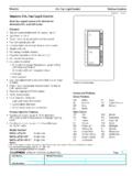
6 This indicates the SPEED switchsensor is properly aligned with the magnetic GREEN LED should be on indicating the monitored shaft is rotating. The switchrelay is energized when the GREEN LED is on. The GREEN LED shuts offapproximately seconds after the monitored shaft stops proper mounting and electrical connections as described in sections3 and the back cover of the SWITCH housing and locate the RED and GREEN LEDlights on the circuit LED LOCATIONRED LEDGREEN LEDThe RED LED flashes every timea magnet passes in front of the GREEN LED lights toindicate the relay is 6A208-05, Page 7 WARNINGP roceed with caution when power is applied to the SWITCH and the back coveris removed. Stay clear of any moving RED LED will remain on if a magnet stops in front of the sensing does not affect SWITCH Control SYSTEMSTMCALL TOLL : PARTS LISTPart , less Bracket and Disc1217A5000 GEC, Mounting Bracket1136 Magnet Disc 4 1378 Magnet Disc 8 A208-05, Page 8 LIMITED WARRANTYP rocess Control Systems, Inc.
7 Will repair or replace, at their option, factory,any part or unit which proves to be defective in material or workmanship within fiveyears of purchase date, provided that part of the unit was installed and operated asrecommended, to be established by examination of the part or unit at the returned under warranty must be shipped prepaid to the factory andaccompanied by the serial number, description of defect, order number and date warranty shall not apply to any MaxigardTMproduct which shall have beenrepaired or altered outside of the Process Control Systems factory or has beensubject to misuse, negligence or Control Systems, Inc. warrants its products, but not their application, andshall not be liable for any incidental or consequential damages incurred through theuse or loss of use of a Process Control Systems product. No representatives orother person is authorized or permitted to make any warranty or assume for thiscompany any liability not strictly in accordance with this is no further warranty either expressed or implied beyond that set Control SYSTEMSTMCALL TOLL.