Transcription of CL608e/CL612e Printers
1 CL608e/CL612e Printers Service manual PN 9001079. Rev. A. SATO America, Inc. 545 Weddell Drive Sunnyvale, CA 94089. Main Phone: (408) 745-1300. Tech Support Hotline: (408) 745-1379. Fax: (408) 745-1309. http:\\ Copyright 2002. SATO America, Inc. The information supplied in this manual was current at time of publication. If you come across procedures that need clarification or find errors or have suggestions contact us at Warning: This equipment complies with the requirements in Part 15 of FCC. rules for a Class B computing device. Operation of this equipment in a residential area may cause unacceptable interference to radio and TV. reception requiring the operator to take whatever steps are necessary to correct the interference. All rights reserved. No part of this document may be reproduced or issued to third parties in any form whatever without the express permission of SATO. America, Inc. The materials in this document are provided for general information and are subject to change without notice.
2 SATO America, Inc. assumes no responsibility for any errors that may appear. PN 9001079 SATO CL608e/CL612e Service manual Rev. A. Table of Contents Section 1. Overview and Specifications Page 1 Overview .. 1-1. 2 Physical Characteristics .. 1-2. 3 Printer Features .. 1-3. 4 Operation PanelDisplays .. 1-5. 5 Components .. 1-7. 6 Switches and Sensors .. 1-8. 7 Ribbon .. 1-10. 8 Installation Considerations .. 1-10. 9 Optional Accessories .. 1-10. 10 Environment & Approvals .. 1-11. 11 General Printer Specifications .. 1-11. 12 Character Fonts .. 1-14. 13 Bar Codes .. 1-15. Section 2. Configuration 1 Dip Switch Settings .. 2-1. 2 Default Settings .. 2-7. 3 LCD Panel Printer Configuration .. 2-8. Normal Mode .. 2-9. M8400 Compatible Mode .. 2-12. Advanced Mode .. 2-13. Card Mode .. 2-17. Service Mode .. 2-25. Counters Mode .. 2-31. Test Print Mode .. 2-32. Default Setting Mode .. 2-33. Maintenance Mode .. 2-34. Clear Non-Standard Protocol.
3 2-36. Download User Defined Protocol Codes .. 2-36. Hex Dump Mode .. 2-37. Download Mode .. 2-38. User Download Mode .. 2-39. 4 Sample Test Labels .. 2-40. Section 3. Interface Specifications 1 Overview .. 3-1. 2 Interface Types .. 3-1. 3 Receive Buffer .. 3-3. 4 IEEE 1284 Parallel Interface .. 3-4. 5 Optional RS232C Serial Interface .. 3-6. 6 Universal Serial Bus (USB) Interface .. 3-9. 7 Local Area Network (LAN) Interface .. 3-10. 8 Bi-Directional Communications .. 3-10. 9 Accessory (EXT) Connector .. 3-19. Section 4. Electrical Checks and Adjustments 1 Overview .. 4-1. 2 Steps Prior to Some Procedures .. 4-2. 3 DC Power Voltage Checks .. 4-3. 4 Potentiometer Assignments & Adjustments .. 4-6. 5a Pitch Offset Adjustment .. 4-8. PN 9001079 SATO CL608e/CL612e Service manual i Rev. A. Table of Contents Section 4. Electrical Checks and Adjustments 5b Pitch Offset Adjustment .. 4-9. 6 Label Gap Adjustment .. 4-10.
4 7 Eye-Mark Adjustment .. 4-11. 8 Feed/Backfeed Adjustment (Tear-Off) .. 4-12. 9 Feed/Backfeed Adjustment (Cutter) .. 4-13. 10 Feed/Backfeed Adjustment (Dispenser) .. 4-14. 11 Ribbon Sensor Verification .. 4-15. 12 Ribbon Sensor Adjustment (Near End) .. 4-16. 13 LCD Display Adjustment .. 4-17. 14 Print Darkness Adjustment .. 4-18. Section 5. Mechanical Adjustments 1 Overview .. 5-1. 2 Ribbon Clutch Adjustments .. 5-2. 3 Print Head Position Adjustment .. 5-5. 4 Print Head Balance Adjustment .. 5-7. 5 Ribbon Roller Adjustment .. 5-8. 6 Feed Roller Adjustment (Label Tracking) .. 5-9. 7 Timing Belt Tension Adjustment .. 5-11. 8 Head Latch Adjustment .. 5-12. 9 Notch/Gap Sensor Adjustment .. 5-13. Section 6. Replacement Procedures 1 Overview .. 6-1. 2 Replacing the Main Circuit Board .. 6-2. 3 Replacing the 6-7. 4 Replacing the Power Supply .. 6-9. 5 Replacing the Stepper Motor .. 6-12. 6 Replacing the Timing Belts.
5 6-13. 7 Replacing the Print Head .. 6-16. 8 Replacing the Platen .. 6-19. 9 Replacing the Ribbon Drive Clutch Washers .. 6-23. 10 Replacing the Ribbon Motion Sensor .. 6-27. 11 Replacing the Paper End Switch (Micro-Switch) and the Bottom Half of the Notch/Gap and Eye-Mark Sensors .. 6-30. 12 Replacing the Top Half of the Notch/Gap Sensor .. 6-34. 13 Replacing the Display Panel or Keyboard .. 6-37. Section 7. Factory Resets 1 Overview .. 7-1. 2 Factory/Service Test Print .. 7-2. 3 Clear Head Counters .. 7-3. 4 Clear Dispenser Counter .. 7-4. 5 Clear Cutter Counter .. 7-5. 6 Clear EEPROM .. 7-6. 7 Sample Test Prints .. 7-7. Section 8. Troubleshooting 1 Overview .. 8-1. 2 Initial Checklist .. 8-2. 3 The IEEE 1284 Parallel Interface .. 8-2. ii SATO CL608e/CL612e Service manual PN 9001079. Rev. A. Table of Contents Section 8. Troubleshooting 4 The RS232C Serial Interface .. 8-4. 5 The Universal Serial BUS (USB).
6 8-4. 6 The LAN Ethernet Interface .. 8-5. 7 Error Signals .. 8-10. 8 Troubleshooting Tables .. 8-11. 9 Head Pattern Examples .. 8-15. 10 Hex Dump Diagnostic Labels .. 8-17. Section 9. Optional Accessories 1 Overview .. 9-1. 2 Label Cutter Kit Installation .. 9-2. 3 Label Dispenser Kit Installation .. 9-6. 4 PCMCIA Memory Expansion Installation .. 9-15. 5 Flash Memory Expansion Installation .. 9-20. 6 Real Time Clock Installation .. 9-22. Section 10. Parts List 1 Overview .. 10-1. 2 Base Cover Assembly .. 10-2. 3 Frame Assembly .. 10-11. 4 Print Head Assembly .. 10-18. 5 Ribbon Assembly .. 10-22. 6 Feed Roller Assembly .. 10-27. 7 Main PCB Assembly .. 10-30. 8 Interface Option .. 10-31. 9 Dispenser Assembly Option .. 10-32. 10 Cutter Assembly Option .. 10-39. 11 PCMCIA Memory Option ..10-43. Index .. Index -1. PN 9001079 SATO CL608e/CL612e Service manual iii Rev. A. iv SATO CL608e/CL612e Service manual PN 9001079.
7 Rev. A. Section Overview and Specifications Overview . The SATO CL608e/CL612e Printers Service manual provides information for installing and maintaining CL608e/CL612e Thermal Transfer Printers . Step-by- step maintenance instructions are included in this manual with typical problems and solutions. It is recommended that you become familiar with each section in this manual before installing and maintaining the printer. The major differences between the CL608e and the CL612 Printers is the resolution of the head and label width. The CL608e with its 203 dpi head provides an economical labeling solution for most applications. It can print labels up to six inches wide. The CL612e provides a higher print resolution, 305. dpi to give laser-quality printing. It is useful when higher resolution is needed for detailed graphic images. It can print labels up to inches wide. The CL Series "e" Printers use a subset of the standard SATO Command Language.
8 The CL608e/CL612e share the same command set, the only differences are the allowable values representing the print positions on the label. These values are specified in "dots" and will vary depending upon the resolution of the printer and the amount of memory available for imaging the label. The allowable range for each printer is specified in a table for those command codes. The sections in this manual cover the following: Section 1. Overview and Specifications Section 2. Configuration Section 3. Interface Specifications Section 4. Electrical Checks and Adjustments Section 5. Mechanical Adjustments Section 6. Replacement Procedures Section 7. Factory Resets Section 8. Troubleshooting Section 9. Optional Accessories Section 10. Parts list PN 9001079 SATO CL608e/CL612e Service manual Page 1-1. Rev. A. Section 1. Overview and Specifications Physical Characteristics Depth Height FRONT. ACCESS DOOR. Width Dimensions C L 608e C L 612e Wide in.
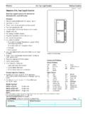
9 (352 mm). D eep in. (430 mm). High in. (298 mm). Weight lbs. (19 kg). Pow er Requirements 115 -220 V (+/- 10%). Voltage 50/60 Hz (+/- 1%). 50W idle Power Consumption 130W Operating Page 1-2 SATO CL608e/CL612e Service manual PN 9001079. Rev. A. Section 1. Overview and Specifications Printer Features INTERFACE SLOT (SHOWN. WITH CENTRONICS PARALLEL. INTERFACE INSTALLED). EXTERNAL. ACCESSORY. CONNECTOR. PCMCIA MEMORY. EXPANSION SLOT. POWER SWITCH. AC FUSE. AC POWER INPUT. CONNECTOR. COVER PLATE-REMOVE FOR. ACCESS TO FAN-FOLD SLOTS. Rear Panel INTERFACE SLOT Slot to plug in an interface adapter. An adapter must be connected before the printer is operational. The adapter types available are: RS232C Serial I/F Module, DP-25P. IEEE1284 Parallel I/F Module, AMP 57-40360. Universal Serial Bus I/F Module Ethernet 10/100 BaseT I/F Module MEMORY CARD SLOT One slot for optional PCMCIA Memory Cards. EXT CONNECTOR External signal connector for Accessories, AMP 57-60140.
10 POWER SWITCH Turns power On/Off AC FUSE Input power protection. Type 3A/250V. AC POWER INPUT Input 115V 50/60 Hz connector. Use the cable provided. PN 9001079 SATO CL608e/CL612e Service manual Page 1-3. Rev. A. Section 1. Overview and Specifications Printer Features RIBBON UNWIND. SPINDLE. ACCESS DOOR LABEL SUPPLY. GUIDE. RIBBON REWIND. SPINDLE. LABEL TEAR. OFF PLATE. MEDIA HOLDER. SWITCHES AND SENSORS. Refer to Section Adjust the Media Knob based on the media you have loaded. For media up to inches wide, use the "1" position. For media between and inches wide, use the "2" position. For media wider than inches wide, use the "3" position. If MEDIA KNOB. you use media narrower than 7 inches, using the wrong setting can void the print head warranty due to excessive pressure. PRINT HEAD MEDIA HOLD. ASSEMBLY DOWN. PLATEN. ROLLER. HEAD LATCH. Page 1-4 SATO CL608e/CL612e Service manual PN 9001079. Rev. A. Section 1. Overview and Specifications Operation Panel/Displays LCD DISPLAY.