Transcription of A99B Series Temperature Sensors …
1 FANs 125, 121, 930, Product/Technical Bulletin A99. Issue Date 0615. a99b Series Temperature Sensors The a99b Series Temperature Sensors are passive PTC (Positive Temperature Coefficient) Sensors . The a99b Sensors are splashproof and are designed to measure Temperature in a variety of refrigeration applications. Several accessories allow easy tailoring of the Temperature sensor to various mounting configurations. Applications include Temperature sensing for freezers and coolers, as well as in defrost termination sensing, space and return air Temperature sensing, and condenser fan cycling. Figure 1: a99b Temperature Sensors Features and Benefits Variety of Lead Lengths Encompasses most application requirements and simplifies wiring Sensors Assortment of Mounting Provides configuration for many Hardware Available applications customizable Very Accurate Sensing Provides excellent performance in a wide Element variety of control applications Stainless Steel sensor Bulb Allows use in more applications than other types of bulbs; no corrosion 2015 Johnson Controls, Inc.
2 1. Part No. 24-7664-1636, Rev. A Code No. LIT-125186. A pplication Overview sensor sensor IMPORTANT: All a99b Series Sensors are designed for use only with operating controls. Where an operating control failure would result in personal injury and/or sensor sensor loss of property, it is the responsibility of the installer to add devices (safety, limit controls). or systems (alarm, supervisory). To Controller that protect against, or warn of, control failure. Figure 2: 4- sensor Averaging Wiring The a99b Temperature sensor line offers an economical solution for a wide variety of sensor sensor sensor Temperature sensing needs in refrigeration and HVAC applications. Typical Temperature sensing applications and environments include: freezers sensor sensor sensor display cases walk-in coolers reach-in coolers sensor sensor sensor defrost termination Temperature sensing condenser fan cycling space and return air Temperature sensing To Controller outdoor air sensing Figure 3: 9- sensor Averaging Wiring process cooling and heating sensor sensor sensor sensor S ensor Temperature Averaging Multiple Sensors may be wired in a Series parallel arrangement to provide an average Temperature sensor sensor sensor sensor reading in an area when one sensor cannot provide a representative Temperature reading.
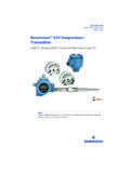
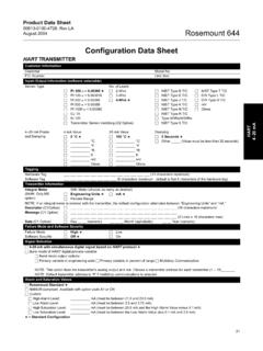
3 This can be accomplished with 4, 9, 16, etc., (22, 32, 42, etc.). Sensors . sensor sensor sensor sensor In a Series parallel arrangement, there must always be the same number of parallel-connected Sensors as there are Series connected Sensors . In Figures 2-4, each parallel leg is represented as a column of Sensors and each Series leg as a row of sensor sensor sensor sensor Sensors . To Controller Figure 4: 16- sensor Averaging Wiring 2 a99b Series Temperature Sensors Product/Technical Bulletin D imensions O peration The a99b sensor incorporates a PTC silicon sensing 1/4 (6) element whose resistance increases with an increase in Temperature . The sensor has a reference resistance of 1,035 ohms at 77 F (25 C). Each element is calibrated 2 (50) according to a standard graph, as shown in Table 2. Figure 5: a99b sensor , in. (mm) The a99b Series Sensors are typically used with Johnson Controls/PENN System 450 controls, MR Defrost controls, MS Multi-Stage controls, and A421 Electronic Temperature Controls.
4 A ccessories The a99b Sensors can also be used with a99b Series accessories include the following: Johnson Controls System 27 NOVA; A255 fan speed control modules; and R78, DX-9100, XP-9102, XPA-4x1, 1 11/16 1 3/8. (42) System 350 controls, A419 Electronic Temperature 9 1/8 1 3/4 (35). controls, and XPA-8x1 products. (229) (44). Sun Shield SHL10A-603R. 4 1/2 M ounting ( ). 4 5/16 Mounting Considerations (110). The a99b sensor may be mounted in virtually any EMT position. To ensure proper operation of the a99b Series PVC Enclosure Conduit BOX10A-600R. Sensors , observe the following guidelines: 1/2 Adapter (13) ADP11A-600R Mount Sensors in areas where they are exposed to representative Temperature conditions and sufficient air mixing. Avoid mounting the Sensors where air 4 3/4. 1. (119) stratification exists. ( ) 3. (76) Dia. Avoid areas subject to excessive mechanical 3/8 vibration or electrical noise.
5 ( ). 1/4 (6). 1. 7/8 For outdoor applications, avoid areas where the (23). ( ) sensor will be exposed to direct sunlight because Surface Mount Clip this causes the sensor to read a higher Temperature . A99-CLP-1 The north side of the building is preferred for outdoor Sensors . If not possible, install a sun shield. Figure 6: Available Accessories, in. (mm). Use a thermally conductive paste where appropriate to improve the thermal contact with the sensor . Do not subject silicon cable (A99BC) to any silicon-based fluids, as this will degrade the cable. a99b Series Temperature Sensors Product/Technical Bulletin 3. Mounting Using an Immersion Well Mounting with a PVC Enclosure 1. Select the mounting location in the pipe line. The PVC enclosure can be mounted in a variety of A 1/2 in., 14 NPT, opening is required to ways. See Figure 6 for mounting dimensions. When properly install the immersion well (WEL11A- mounting the PVC enclosure, refer to the Mounting 601R).
6 The pipe's diameter must be greater Considerations section, as well as the following: than the length of the well probe. To minimize false readings caused by air movement 2. Insert an appropriate amount of thermally through the conduit hole, seal that part of the conductive paste in the well. enclosure after the sensor has been inserted. 3. Install the immersion well. Tighten hex nut If a conduit connection is required, snap the conduit securely using a wrench. adapter into the bottom opening of the enclosure and tighten the adapter's set screw. Tighten with Wrench 1. Loosen the two PVC enclosure screws and remove the front plate. 1/2 inch 14 NPT. Opening sensor Clip Front Plate PVC Enclosure Screws Figure 7: Installing the Immersion Well 4. Using a straight slot screwdriver, loosen the set screw at top of the immersion well. 5. Thread the spring, then the bushing, onto the sensor lead.
7 sensor Figure 9: PVC Enclosure 2. Thread the sensor through the bottom opening and snap the sensor in the sensor clip inside the PVC. enclosure. 3. Replace the front plate on the PVC enclosure and firmly tighten the screws. Figure 8: Insert sensor , Spring, and Bushing 6. Insert sensor , spring, and bushing into well, so that at least one-half of the bushing is inserted into the well, as shown in Figure 8 (bushing will compress spring). 7. Tighten the set screw against the bushing. 4 a99b Series Temperature Sensors Product/Technical Bulletin W iring C heckout Procedure Before applying power, make sure installation and wiring ! WARNING: Shock Hazard. Disconnect all connections are according to job specifications. After necessary adjustments and electrical connections have power to the controller that the been made, operate the system and observe at least sensor is connected to before three complete cycles before leaving the installation.
8 Wiring or servicing. For wiring, follow the instructions below: Troubleshooting Make sure all wiring conforms to the National Check the sensor for proper resistance: Electric Code and local regulations. 1. Disconnect the sensor from the control. Run high and low voltage wiring in separate conduits. For applications in critical industrial 2. Take a Temperature reading at the sensor location. environments, use a sensor with a shielded Be sure to let the thermometer stabilize before cable (A99BA). taking a reading. If wire is added to the sensor leads, additional 3. Use the Temperature reading from Step 2 to resistance may affect the sensor reading. determine the expected sensor resistance from Longer wires increase resistance, which causes Table 2. a shift in the sensor Temperature reading. 4. Using an ohmmeter, measure the actual resistance Note: At the wire lengths listed in Table 1, the across the two sensor leads.
9 Error in the sensed Temperature is less 5. Compare the expected resistance to the actual than 1 F ( C). resistance. Table 1: Maximum sensor Wire Lengths 6. If the sensor 's actual resistance deviates (for less than 1 F error) substantially from the expected resistance found in Table 2, replace the sensor . Wire Gauge Wire Length AWG Feet Meters 14 AWG 800 244. 16 AWG) 500 152. 18 AWG 310 94. 20 AWG 200 61. 22 AWG 124 38. Shielded Cable Models (A99BA) Only: For all controls, including the Johnson Controls/PENN. System 350, MR, MS, and A419, connect the sensor cable shield to the controller per the controller's instructions. a99b Series Temperature Sensors Product/Technical Bulletin 5. Table 2: Resistance vs. Temperature 260. 240. F ( C) Resistance F ( C) Resistance 220 in Ohms in Ohms 200. Temperature ( F). 180 -40 (-40) 613 113 (45) 1195. 160. 140 -31 (-35) 640 122 (50) 1237.
10 120. 100 -22 (-30) 668 131 (55) 1279. 80. 60 -13 (-25) 697 140 (60) 1323. 40. 20 -4 (-20) 727 149 (65) 1368. 0. -20 5 (-15) 758 158 (70) 1413. -40. 500 700 900 1100 1300 1500 1700 1900 2100. 14 (-10) 789 167 (75) 1459. Resistance in Ohms 23 (-5) 822 176 (80) 1506. 32 (0) 855 185 (85) 1554. Figure 10: Resistance Scale for 41 (5) 889 194 (90) 1602. Fahrenheit temperatures 120 50 (10) 924 203 (95) 1652. 100 59 (15) 960 212 (100) 1702. Temperature ( C). 80 68 (20) 997 221 (105) 1753. 60 77 (25) 1035 230 (110) 1804. 40 86 (30) 1074 239 (115) 1856. 20. 95 (35) 1113 248 (120) 1908. 0. 104 (40) 1153. -20. -40. 500 700 900 1100 1300 1500 1700 1900 2100. sensor accuracy is within ( ) between 5 and 167 F (-15 and 75 C). Tolerance increases at Resistance in Ohms temperatures outside this range, as shown in Figure 12. Figure 11: Resistance Scale for ( ). Celsius temperatures Error from Nominal F (C ).