Transcription of AC 20-143 - Installation, Inspection, And Maintenance Of ...
1 Advisory us. Depanment of TransportatiOn CircularFederal IINiation Administration Subject: installation , INSPECTION, AND Date: 6/06/00 ACNo: 20-143 Maintenance OF CONTROLS FOR Initiated By: ACE-100 Change: GENERALAVIATIONRECIPROCATING AIRCRAFT ENGINES 1. PURPOSE. A review of service history on engine control installations indicates that a significant percentage ofthe problems are related to Maintenance . Of the control system problems related to Maintenance , approximately 75 percent ofthe problems with these systems result from lack ofproper Maintenance of airplane manufacturer installed engine controls. The other 25 percent ofthe service problems originate from a lack of Maintenance of the engine manufacturers' throttle, mixture, and propeller governor levers/linkages. Most airplane or engine Maintenance manuals lack detailed information on inspection and installation of engine controls.
2 Therefore, this advisory circular (A C) presents information regarding the inspection, Maintenance , and instaliation of engine controls with emphasis on the airframe portion ofthese systems. It provides guidance to design and Maintenance personnel to reduce the number of airplane accidents and incidents related to the loss of engine power control. This material is neither mandatory nor regulatory in nature and does not constitute a regulation. This AC is provided to supplement, but not replace the procedures in the manufacturers' Maintenance manuals. Where the content ofthis AC differs from, or conflicts with, the manufacturer's Maintenance manual, instructions contained in the manufacturer's manual take precedence over the guidelines provided in this AC. 2. RELATED REGULATIONS. Title 14 Code of Federal Regulations (14 CFR) Part 21, Airplane airworthiness regulations are specified in 14 CFR Part 23, , , , , and , and the corresponding Civil Air Regulations (CAR) under Part 3.
3 Engine airworthiness regulations are specified in 14 CFR Part 33, , and , and their corresponding CAR under Part 13. Propeller airworthiness regulations are specified in 14 CFR Part 35, , and the corresponding CAR under Part 14. Inspection requirements can be found in 14 CFR Part 43, appendix D, and (c). 3. BACKGROUND. Current 14 CFR design rules require throttle and mixture controls on single reciprocating engine-powered airplanes that will allow continued safe flight and landing in the event of a control separation at the engine fuel metering device. The current rules ( (g) and (b)) are not applicable to older airplanes. This AC has been prepared to address proper AC 20-143 6/06/00 installation , inspection, and Maintenance of many different types of engine controls on airplanes old and new regardless of the rules under which they were certified.
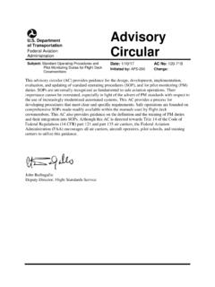
4 General requirements are contained in Part 43, appendix D, which specify the scope and detail of items to be included in annual and 100 hour inspections, ofwhich paragraph (d)(6) states, "Engine controls-for defects, improper travel, and improper safetying." This AC will provide expanded guidance for general aviation airplanes equipped with reciprocating engines. 2 6/06/00 AC 20-143 4. DEFINITIONS. a. Rod End. A machined fitting on one end ofa control cable or rod, which is usually threaded on one end and has a hollow ball and socket at the other end, that allows a swivel motion at the engine lever attachment (see figure 1 ). FIGURE 1. LINKAGE CONNECTION TO ENGINE l. CLAMP 2. BRACKET 3. MIXTURE CONTROL ARM 2 l 12 109 4. RODEND 5. AIR THROTTLE ARM 6. RODEND 7. MIXTURE LINK ROD 8. THROITLE LINK ROD 9. THROTTLE BELL CRANK 10. MIXTURE BELL CRANK 11.
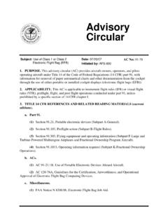
5 ROD END 12. RETAINING RING 6 13. RODEND 14. RETAINING RING 15. THROTTLE CONTROL 16. MlXTURE CONTROL NOTE: For guidance information only. May not represent actual installations. 3 AC 20-143 6106/00 b. Secondary Retainment Washer. A large load-bearing washer adjacent to the outside face of rod end fitting (see figure 2). FIGURE 2. ROD END SAFETY PROCEDURE USING SECONDARY WASHER RETAINMENT THROTTLE CONTROL LEVER ROD END BEARING WASHERS SECONDARY RETAINMENT WASHER NOTE: For guidance information only. May not represent actual installations. 4 6/06/00 AC20-143 c. Swaged Joint. A connection of a cable end to a rigid rod or tube (usually by staking or crimping) that transmits cable motion to the engine control lever. d. Alternate Air Control. A flexible or rigid control attached to a small door at the carburetor air inlet, or fuel-injector throttle body, that allows entry of heated air or sheltered compartment air.
6 E. Fire Sleeve. A protective sleeve covering ( , steel, aluminum, asbestos) added to a control cable or rod end connection that provides local heat or fire protection. 5. INSPECTION PROCEDURE-GENERAL. The need for the correct installation ofthe engine control cable, attaching hardware, and fuel system component levers and linkages cannot be overemphasized. The use of approved attachment procedures and techniques is required to assure proper operation and to prevent accelerated wear. CAUTION Replacement of rotatable powerplant controls capable of knob rotation at the instrument panel with non-rotatable solid shaft controls is discouraged. Solid shaft controls (non-rotatable at the instrument panel knob) have been found disconnected at the rod end as a result of pilots attempting to adjust a friction lock without realizing that the knob was also being rotated.
7 Solid shaft powerplant controls may be replaced with rotatable knob controls when acceptable data exists. a. L'l the absence of specific inspection intenrals, repetitive inspections of the engine controls in the nacelle and cockpit areas should be conducted as part of the annual and 1 00-hour inspections described in Part 43, appendix D. b. Inspect all engine control cables for proper tension, routing, security, and signs of damage caused by chafing and heat distress. Improper installation of cables will significantly reduce their service life. c. In addition to the throttle and mixture controls, inspect the operation of each engine-related control such as the propeller, carburetor heat, alternate air, and cowl flap controls as applicable. Make certain that each control has full limit oftravel, and that no binding or excessive play caused by worn parts or improper installation is evident.
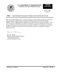
8 D. Apply simulated air loads by manually pressing on cowl flaps and alternate air controls to ensure cables are not slipping in support clamps. Check for looseness ofthrottle, mixture, and propeller controls to ensure proper security ofthese components. e. Replace all control cables, levers, link rods, and attaching hardware found damaged or worn beyond acceptable service limits. Engine-related levers, link rods, and attaching hardware should be installed in accordance with the instructions provided in the applicable aircraft or engine Maintenance manuals. Consult the airframe/engine manufacturer's published 5 AC 20-143 6/06100 instructions for routing and attaclunent of the various engine-related control cables. Attaclunent of components that have relative motion should be accomplished by using bolts (screws) drilled for cotter pins, using castellated nuts, cotter pins, and large secondary washer retention devices.
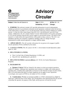
9 (See figures I, 2, and 3.) WARNING: Connections requiring torque fasteners should not exhibit any relative movement or motion between components. FIGURE 3. CABLE RETENTION METHOD " s ~g~-CONTROL '\._ , CABLES I ~ NOTE: For guidance information only. May not represent actual installations. 6 6/06/00 AC 20-143 6. LUBRICATION OF CONTROL RODS, LINKAGES, AND JOINTS (see figures 4 and 5). Damage and wear to the actuating components ofengine control systems can be attributed to improper (or the lack of) lubrication. During scheduled and unscheduled Maintenance , engines are normally cleaned using a solvent or soap solution pressure wash. This tends to remove lubrication from fuel system levers, linkages, and bushings. Therefore, it is necessary that these areas be lubricated after engine cleaning and during scheduled Maintenance as indicated in the following paragraphs: a.
10 Consult with the airplane and engine manufacturers, plus the control cable manufacturer if necessary, for published instructions covering powerplant control cable service-life limits and attach-point inspection, repair, installation , and lubrication. b. Inspect the pivot points ofthe levers and linkages for dirt, wear, and rust, and replace as necessary. Direct cleaning ofthese areas may be necessary to remove contamination including a buildup of old grease or oil. After cleaning with clean solvent or soap solution, dry each area using compressed air. 7 AC 20-143 6/06/00 FIGURE 4. SOLID ROD LINKAGE LUBRICATION NOTE: For guidance information only. May not represent actual installations. 8 6/06/00 AC 20-143 FIGURE 5. SOLID ROD ADJUSTMENT AND LUBRiCATION 0 = REFERENCE THE AIRFRAME MANUFACTIJRER'S installation . CLEANING AND LUBRICATION instructions NOTE: For guidance information only.