Transcription of AC Ripple Current Calculations - Vishay
1 Technical questions, contact: Number: 4003122 Revision: 03-Apr-06AC Ripple Current CalculationsVishay SpragueApplication Notes AC Ripple Current Calculations Solid Tantalum CapacitorsINTRODUCTIONS olid tantalum capacitors are preferred for filteringapplications in small power supplies and DC/DC convertersin a broad range of military, industrial and commercialsystems including computers, telecommunications,instruments and controls and automotive equipment. Solidtantalum capacitors are preferred for their high reliability,long life, extended shelf life, exceptional stability withtemperature and their small size.
2 Their voltage range is 4 to50 volts for the most common types. Tantalum chipcapacitors for surface mount applications are manufacturedin very small sizes and are compatible with standardpick-and-place electronics industry has moved to smaller and smallerpower supplies and higher switching frequencies, with anincreased requirement for capacitors with smaller size andoperating characteristics better suited to high application note briefly describes the construction ofsolid tantalum capacitors, the concept of Equivalent SeriesResistance (ESR)
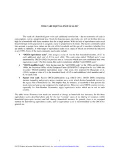
3 And presents Calculations for powerdissipation and voltage limitations for both low and highfrequency solid tantalum capacitor consists of a sintered tantalumpellet, the anode, on which a tantalum oxide dielectric isformed by electrolysis. The pellet is then coated withmanganese dioxide for the cathode. Positive and negativeterminations are attached to this pellet and the assemblymay be conformally-coated or molded. Looking closely at the internal structure of the pellet, we seethat it is made of grains of tantalum powder sintered to eachother.
4 A solid tantalum capacitor is equivalent to many smallcapacitors in parallel, one for each grain of powder. Thisconfiguration produces a very large surface area, therefore alarge capacitance in a relatively small volume. CONFORMAL COATED SERIESTANTALUM PELLETMOLDED SERIESC athode Termination(Silver + Ni/Sn/Plating)EncapsulationAnode Termination(Silver + Ni/Sn/Plating)Red Epoxy TowerSintered Tantalum PelletMnO2/Carbon/SilverCoatingTANTAMOUN T , Solid Electrolyte Tantalum Chip ViewMetallized OuterElectrodeCarbonMnO2Ta2O5 TantalumTantalum Anode LeadAnode Polarity BandTopMarking SurfaceBottomSideEndSilver AdhesiveSolderable CathodeTerminationSintered TantalumPelletLead FrameSolderableAnode TerminationAnode Polarity BarEpoxy EncapsulationMnO2/Carbon/SilverCoating Document Number: 40031 For technical questions, contact.
5 03-Apr-0623AC Ripple Current CalculationsApplication Notes AC Ripple CurrentCalculations Solid Tantalum CapacitorsVishay SpragueEQUIVALENT SERIES RESISTANCE (ESR)A capacitor offers intemal resistance to AC Current , calledthe Equivalent Series Resistance (ESR). At lowerfrequencies, this is mainly the resistance of the dielectric. Athigher frequencies, the resistance of the manganese dioxidein the voids between the grains is predominant. Because theresistivity of manganese dioxide is inversely proportional totemperature, the ESR of solid tantalum capacitors at highfrequencies decreases as temperature DISSIPATION LIMITATIONWhen AC Current is applied to a solid tantalum capacitor, theresistance (ESR) that opposes the flow of Current results inheat generation, according to the formula:(1) The power (P) dissipated in the capacitor results in anelevation of temperature.
6 The allowable temperature rise ofa capacitor due to power dissipation is determined byexperience. For example, this value is + 20 C maximum formolded chip capacitors. This in turn limits the power that thecapacitor can LIMITATIONThe power a capacitor can dissipate is also limited by theapplied DC voltage. The operating voltage should not beallowed to rise above the rated voltage (nor should it dropbelow zero, since the solid tantalum capacitor is a polarizedcomponent). Assuming the capacitor is biased at half therated voltage, which is the optimum use condition, thelimiting value of the voltage is, for a sinusoidal waveform:(2) Vrms for each value of Rv (Rated voltage) are: Current LIMITATION (LOW FREQUENCY)To find the limiting Current Irms, we divide Vrms by theimpedance at the desired frequency.
7 (3) using the formula:(4) where X is 1/Cw + Lw (w = 2pf)Since inductance of a solid tantalum capacitor is usually inthe nanohenry range, the Lw factor becomes important onlywhen the frequency is higher than a few megahertz. Forfiltering applications at 100 kHz and lower, the inductancefactor will generally be ignored in the calculation . At 120 Hz,the impedance can be determined by calculation .(5)At 120 Hz, DF2 is relatively small compared with 1 and theformula can be simplified to:(6) More generally, DF values of less than 10 % will not affectthe final result by more than 1 %.
8 It is important to use thelowest value for C, including the capacitance tolerance. At120 Hz, the formula can be simplified to:(7) where Irms is the maximum permissible rms Current inmilliamperes, C the capacitance minus the capacitancetolerance in microfarads and V the rated voltage in volts. Allabove Calculations assume the capacitor is properly biasedat half the rated voltage. If this is not the case, Vrmsbecomes(8) where Vp = V rated - V bias or V bias, whichever is VOLTAGEVrms =VrmsVpp 2 2 Rv 2 2 ==IrmsVrms Z =ZX2 ESR2+=Z12 fC ()2DF 2 fC ()2+12 fC ()1DF2+()==Z12 fC = CV =Vp2 AC Ripple Current CalculationsVishay SpragueApplication Notes AC Ripple CurrentCalculations Solid Tantalum technical questions, contact: Number: 4003124 Revision.
9 03-Apr-06 Current LIMITATION (HIGH FREQUENCY)At frequencies in the 10 kHz to several hundred kilohertzrange, the power dissipation becomes the limiting factor. Thefollowing formula gives the maximum permissible ripplecurrent for a sinusoidal wave form:(9) Pmax is the maximum power dissipation the capacitor cantolerate. The ESR value in the formula is the maximum ESRof the capacitor at the required frequency. This can bedetermined by measuring capacitors and determining amaximum value by using the mean value and adding 3 ormore standard deviations.
10 Some manufacturers specify themaximum impedance at 100 kHz or 1 MHz. Either value maybe used in Ripple Current Calculations . Power dissipation limits calculated for the most popularsurface mount types of solid tantalum capacitors are: Molded Case Chip (293D):ESR SCREENINGFor parallel operation, the ESR spread can be minimized byscreening. This reduces the risk of excess Ripple currentexposure to any one of the equipment will only measure impedance. Animpedance limit can be caluclated to insure that the ESRstays in the required range.