Transcription of ACCESSORY KIT INSTALLATION INSTRUCTIONS - …
1 Johnson Controls Unitary Products247589-UAI-F-0210 ACCESSORY KIT INSTALLATION INSTRUCTIONSPROPANE CONVERSION 1NP0680 FOR USE WITH ALL MODULATING FURNACE MODELS WITH WHITE RODGERS 36E27 GAS VALVE GENERALThis kit is intended for the conversion of new equipment only,from natural gas to propane gas instruction covers the conversion of this unit when it isequipped with a White-Rodgers modulating 36E27 gas INSTALLATION instruction supplied with the unit is to be usedfor all other aspects of the kit cannot be used to convert furnaces built after August2009 which have the White-Rodgers 36J27 gas valve. Theseunits must use the S1-1NP0681 LP conversion kit is to be installed by a qualified service agency in accordance with these INSTRUCTIONS and all applicable codesand requirements of the authority having jurisdiction. If the information in these INSTRUCTIONS is not followed exactly, a fire, anexplosion or production of carbon monoxide may result causing property damage, personal injury or loss of life.
2 The qualifiedservice agency is responsible for the proper INSTALLATION of this kit. The INSTALLATION is not proper and complete until the operationof the converted appliance is checked as specified in these INSTRUCTIONS supplied with the conversion of new certified central heating gas appliances must conform to directions outlined in this instruction. INSTALLATION must be made in accordance with American National Standard National Fuel Gas Code, ANSI edition,unless superseded by local codes. For Canadian installations, the conversion shall be carried out in accordance with the require-ments of the Provincial authorities having jurisdiction and in accordance with the and .2 INSTALLATION codes. The manufacturer accepts no responsibility for malfunctions due to improper conversionsLo-NOx furnaces requiring propane (LP) gas must have the NOx screens removed prior to operation. Failure to do so may resultin operational problems and/or reduced heat exchanger life.
3 Follow the INSTRUCTIONS below for removal of the NOx original equipment gas valve on the furnace is notcapable of being adjusted so as to operate on LP gas pres-sures. The new gas valve in this kit must be INSTRUCTIONS are for the use of qualified individualsspecially trained, experienced and certified in the installationof this type of equipment and related systems and service personnel are required by somestates to be licensed. Persons not qualified shall not installthis equipment nor interpret these INSTALLATION , adjustment, service or maintenancecan cause injury or property damage; therefore, only a qual-ified installer or qualified service personnel should performthis overpressure protection device, such as a pressure reg-ulator, which conforms to the National Fuel Gas code, ( ) or (Canada) and acts to limitthe downstream pressure to value that does not exceed (14" ), must be installed in the gas piping systemupstream of the furnace.
4 Failure to do so may result in a fireor explosion or cause damage to the furnace or some of OF KITD escriptionPart NumberQtyGas Line Pressure Switch174711 Tapped Gas Pipe Nipple180951 Modulating Gas Valve (Red Knob)1672461 Kit INSTALLATION Instruction2475891 Main Burner Orifices #55180816 Wire Harness204611 Label, Conversion Rating Plate2556491 Label, LP Conversion Kit2554241 Label, Conversion Kit 90%2558121247589-UAI-F-02102 Johnson Controls Unitary ProductsSAFETYThis is a safety alert symbol. When you see this symbolon labels or in manuals, be alert to the potential for per-sonal and pay particular attention to the signal wordsDANGER, WARNING, or CAUTION. DANGER indicates an imminently hazardous situation, which, ifnot avoided, will result in death or serious indicates a potentially hazardous situation, which, ifnot avoided, could result in death or serious indicates a potentially hazardous situation, which, ifnot avoided may result in minor or moderate injury.
5 It is alsoused to alert against unsafe practices and hazards involvingonly property the upper access remove the wires from the gas valve and notetheir location so they may be properly replaced. Removethe screws that hold the manifold to the manifold bracketsand slide the manifold off the 80% Low-NOx models, remove NOx screens usinginstructions in separate section the natural gas valve from the the LP gas valve from this kit, making sure that it istight and in approximately the same position as the the main burner orifices from the manifold andretain for future the propane main burner orifices in the manifold andtighten them. After installing a propane orifice in each loca-tion, any leftover orifices may be discarded. If a stainlesssteel burner kit was purchased, refer to the kit instructionsfor the burner change the manifold in the assembly by reversing the removal the wires to the proper terminals on the Install the tapped gas pipe nipple (supplied with kit) intoinlet fitting of gas valve.
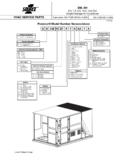
6 Ensure that the 1/8 inch tappedhole in the gas pipe nipple is located in the horizontal Install (thread) the gas line pressure switch (supplied with kit) into the 1/8 NPT tapped hole in nipple applying pipe dope to the switch fitting prior to INSTALLATION . Tighten the switch making sure the connection does not Disconnect the purple wire from the flame Using the appropriate wire harness (supplied with kit) con-nect the purple wire from the flame sensor into the insu-lated male connector; connect the two 1/4 insulatedterminals to the pressure switch; and connect the remain-ing insulated terminal to the flame Install the propane gas conversion label as described in theLABELS section of this Refer to the unit INSTALLATION INSTRUCTIONS to complete theinstallation before continuing with these SCREEN REMOVAL (LOW-NOx 80% MODELS ONLY) entire burner and discard NOx screens from heat burner gas supply shall be shut off prior to disconnecting theelectrical power, before proceeding with the 1: Tapped Gas Pipe NippleThe gas line pressure switch will cause the furnace to lockout if the gas supply pressure drops below 6 The igni-tion control will display a fault code 7 and will reset after barbed connector on the gas valve labeled VENT (seeFigure 1) should be used only with furnace models having aclosed burner box.
7 For furnaces without a closed burnerbox, the barbed connector must be left Controls Unitary Products3 CALCULATING THE FURNACE INPUT(PROPANE GAS) off all gas appliances connected to the gas the a stop watch to measure the time it takes for the fur-nace to burn 1 cubic ft. of the furnace input by using one of the the following formula to calculate the furnace propane (LP) gas multiply the heat content of the gas BTU/SCF or Default 2500 BTU/SCF ( MJ/m3), times 1 cubic ft. ( m) of gas measured at the gas meter, times a barometric pressure and temperature correction factor of ; times 3600, then divided by the time (In seconds) it took to measure 1 cubic ft. ( m) of gas from the gas formula for US input calculation using a cubic foot gasmeter:DO NOT ADJUST the manifold pressure regulator if the actual input is equal to or within 8% less than the furnace input speci-fied on the rating plate or if the furnace rise is above the speci-fied rise range on the rating the actual input is significantly higher than the furnaceinput specified on the rating plate then replace the gas ori-fices with the gas orifices of the proper size for the type of gasyou are OF MANIFOLD GAS PRESSUREF ollow the appropriate section in the INSTRUCTIONS below.
8 Referto Figure 1 for a drawing of the locations of the pressure portson the gas gas off at the ball valve or gas cock on gas sup-ply line before the gas valve. Find the pressure ports on the gas valve marked OUT P and IN manifold pressure must be taken at the port markedOUT P. inlet gas line pressure must be taken at the portmarked IN a 3/16 allen wrench, remove the plugs from the inletand outlet pressure ports. Connect a 1/8 UPT barbedhose fitting to each pressure models without a sealed burner box, continue to Step models with a sealed burner box, read the inlet gas pres-sure using the method the pressure reference hose from the right sideof the burner box. Using a tee fitting and a short piece ofhose, connect the negative side of the manometer to theburner box as described one end the 5/16 ( mm) ID flexible tubingover the pressure port on the burner box.
9 The end of the 5/16 ( mm) tubing, that has the 1/8 ( mm) adapter at the end of the tube, in to the 1/8 ( mm) the 1/8 ( mm) tee to the burner box adapterand to the negative side of a U-tube manometer or digitalpressure measuring equipment with 2 1/8 ( mm) the 5/16 ( mm x 1/8 ( mm) reducing cou-pling and a 4 ( mm) piece of 1/8 ( mm) tubingto connect the positive side of the manometer to the gasvalve pressure reference orifices are sized to provide the proper input rateusing propane gas with a heating value of 2500 BTU/Ft3. Ifthe heating value of your gas is significantly different, it maybe necessary to replace the orifices with different size ori-fices. Follow the procedure below to calculate the x 1 x x 3600=BTU/HSeconds it took to measure the 1 of gasPROPANE (LP) GAS INPUT CALCULATIONEXAMPLE:2500 x 1 x x 3600=80, GasBTU/SCF 2500 TABLE 1:Inlet Gas Pressure RangeINLET GAS PRESSURE RANGEP ropane (LP) ( kPa) ( kPa)NOTICEThe inlet gas pressure operating range table specifieswhat the minimum and maximum gas line pressures mustbe for the furnace to operate gas line pressure MUST BE 11 ( kPA) for Propane (LP) Gasin order to obtain the BTU input specified on the rating plateand/or the nominal manifold pressure specified in theseinstructions and on the rating models without a sealed burner box, connect themanometer hose to the barbed hose fitting.)
10 For models witha sealed burner box, connect the manometer as describedin the section to change without notice. Published in 2010 by Johnson Controls, Inc. All rights : 247589-UAI-E-0709 Johnson Controls Unitary Products5005 York DriveNorman, OK to Figure 1 for location of pressure regulator adjust-ment cap and adjustment screws on main gas Turn gas and electrical supplies on and follow the operat-ing INSTRUCTIONS to place the unit back in Adjust manifold pressure by adjusting gas valve regulatorscrew for the appropriate gas per the following:12. After the manifold pressure has been adjusted, re-calculatethe furnace input to make sure you have not exceeded thespecified input on the rating plate. Refer to CALCULAT-ING THE FURNACE INPUT (PROPANE GAS) .13. Once the correct BTU (kW) input has been established,turn the gas valve to OFF and turn the electrical supplyswitch to OFF; then remove the flexible tubing and fittingsfrom the gas valve pressure tap and the pressure refer-ence hose from the right side of the burner box and tightenthe pressure tap plug using the 3/32 ( mm) Allenwrench.