Transcription of After all Pulley Caps are tight reinstall the outer ...
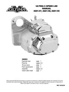
1 ASSEMBLY DIAGRAM AND ASSEMBLY REFERENCE ULTIMA SOFTAIL BELT DRIVES 1990-2006 Part # 58-700 DRAG STYLE, CAST, POLISHED58-730 STREET STYLE, CAST, POLISHED58-800 DRAG STYLE, BILLET, POLISHED58-801 DRAG STYLE, BILLET, MACHINEDREV 6-4-14 VII. INSTALLING THE OUTBOARD BEARING SUPPORTA fter all Pulley caps are tight reinstall the outersupport plate using Blue Loctite. Torque Bolt to 15-18ft Motor Pulley and Trans Pulley caps using Blue Loctite. Snugbolts only. Install the preassembled outer support plate assemblystarting with the clutch basket side. With a small hit of the handpushing towards the clutch basket side the outer support plateshould snap in. Snug the outer support plate with the 2 center boltsonly. Using the Starter Motor With the plugs out of the engine rotatethe belt drive a few times to insure the Pulley caps get centered. Get2 or 3 bolts tight on the caps 120-140 in lb.
2 Remove the outersupport plate and torque all Pulley cap bolts. your kickstand clearance to the belt pushing down on the belt thenadding at lease 1/2 .Use MWM # 5-190 Adjustable Kickstand Leg Stop if DIAGRAM AND ASSEMBLY REFERENCE ULTIMA 8MM BELT DRIVE UNITS BELT DRIVE PRODUCTSWARRANTY PROVISIONSU ltima s component parts used in our Belt Drives are guaranteed to the original purchaser to be free of manufacturing defects in materialsand workmanship for a period of Twelve (12) months from the date of purchase through Midwest Motorcycle that fails to conform to these conditions will be repaired by Ultima if the parts are returned to Midwest Motorcycle Supply by thepurchaser within the 12-month warranty period or within 10 days problems can be rectified by a telephone call and need no further course of action. A part that is suspected of being defective must notbe replaced by a Dealer without prior authorization from Midwest Motorcycle Supply.
3 If it is deemed necessary for Ultima to make anevaluation to determine whether the part was defective, it must be packaged properly to prevent further damage and be returned prepaid toMidwest Motorcycle Supply with a copy of the original invoice of purchase and detailed letter outlining the nature of the problem, how the partwas used and the circumstances at the time of failure. If, After an evaluation has been made by Ultima and the part was found to bedefective, repair or replacement will be granted at Ultima s WARRANTY PROVISIONS:1. Ultima shall have no obligation in the event an Ultima part is modified by any other person or Ultima shall have no obligation in the event an Ultima part becomes defective in whole or in part as a result of improper installation,improper maintenance, improper use, abnormal operation, or any other misuse or mistreatment of the Ultima Ultima shall not be liable for any consequential or incidental damage resulting from the failure of an Ultima part, the breach of anywarranties, the failure to deliver, delay in delivery, delivery in non-conforming condition.
4 Or for any other breach of contract or duty betweenUltima and a These Diagrams are provided for a reference only and in no way imply that this part is suitable for the applications it is being installed Part # s these Diagram reference were designed to fit OEM Softail Style Motorcycles made from 1990-1999 with exception to thestarter drive assembly which uses the 1989-1993 diameter jackshaft bolt (1/4-20). These Drives will also fit most aftermarket Softail and RigidFrames designed to use Softail style components made within these INSTALLATION REQUIREMENTS:Ultima Belt Drives should be installed by trained professional mechanics into motorcycle in which they were intended for use. Failure to do somay result in injury and even death. It is the customer s responsibility to insure their mechanic has proper PREPARATION FOR ASSEMBLYB efore installing the Ultima Belt Drive System you must remove your entire existing primary drive.
5 This also includes the pressed ontransmission mainshaft race used with chain drive inner primary stated earlier the Ultima Belt Drive System requires the use of a 1989-1993 type starter drive shaft which utilizes the larger 1/4-20fastener. We also suggest using any of our heavy duty Ultima Thunder Fire Starters part # 70-220 thru 70-229 which incorporate both 89/93and 94/Later style drive shaft bolt arrangements. These starters are available in , , and Kw 1999 & earlier models, Ultima Belt Drives utilize a slightly longer center distance between the Pulley s and will require that you loosenthe transmission mounting bolts to allow the transmission move back approx .040 . At this time we suggest inspection of your Charging System. Ultima Belt Drives are designed to work with most 32 amp Charging System onthe market today. Later model 38, 40 and 44 amp systems may interfere with the Motor Plate.
6 While you are inspecting the alternator we highly recommend that you install a new Crankshaft Seal on the engine replacing the existingseal with a High Quality double lip seal and installing the seal with the steel face out. Belt Drive Units require a dry environment free from Oiland by flipping the oil seal you ensure any crankcase pressure and oil will stay in your engine. This is also a great time to inspect thetransmission sprocket and seal for wear and to ensure the sprocket is INSTALLING THE CLUTCHC heck the pressure plate screws to ensure they are all tightand the heads of the bolts are sitting below the platesurface. Install the clutch adjusting screw using a smallamount of high temp grease on the thread and especiallyon the Clutch Pushrod end. Don t get to much grease outthere Remember this is a DRY Belt Drive utilize the old style 900cc sportstersteel drive plates and 9 special size fiber platesdesigned to provide a very adjustable Clutch Installing the Clutch Pack Install the Thick.
7 119 Steel Plate First then Alternate Fiber/Steel. The LastPlate you install should be the witness marks on the pressure plate andinner clutch hub as shown when assembling. the Inner Stud Alignment using the clutch spring collar flippedover with the flange side in. The Collar should pass through thepressure plate freely a minimum of 1/4 . Straightening is generally notrequired but if needed straighten the stud by using a small brass your starter motor to the Motor Plate then install the starter drivegear assembly in the order shown using Blue Loctite. The Starter DriveGear should be a Minimum of .150 from the clutch basket starter ringgear once installed. APPLY SOME HIGH TEMP GREASE TO THESTARTER END CAP BUSHING then install the cap using Blue to 18-22ft lb. Reapply grease to bushing every 6 months - DONOT RUN DRY! marksStarter Gear Assembly58-718 Starter Bolt.
8 (1) (90 -93 Starter OEM / Thunderfire), Bolt . (1) (94 & later Starter OEM) Not included, sold the clutch springs and clutch spring guides with the flanges the Clutch Spring nuts until you measure .350 +/- .010 from theface of the pressure plate to the face of the spring guide as sets the Spring at approx. installed height. For higherpower applications go in to .100 measured max for installedheight. Ultima Belt Drives come with a standard pressure spring formost applications under 100 hp. MWM #58-776 Clutch Spring - Medium, Gold (68lb @ 1 )Pressure 42lb @ 68lb @ The clutches grip is adjusted by the spring tension and your clutchlever pressure goes up with spring pressure. For Higher HorsepowerApplications we offer: MWM # 96-252 Clutch Spring - Heavy Duty, Black (82lb @ 1 )# 96-253 Clutch Spring - Extra Heavy Duty, Red (105lb @ 1 ) : CENTER PUSHROD IS REQUIREDThe center clutch push rods (located in thetransmission main shaft) may need to be changeddepending on setup.
9 Below is a list of availble # 1987-1989 5 1990+ 5 1985+ 5 & 6 speedMake sure the jackshaft can be pushed . If you cannot then the spring may becoil-bound. The jackshaft needs thismovement in order to locate and mesh withthe ring gear. Spacers may need to beadjusted accordingly. See figure: Force in F direction should give you 1/8 space inlocation B . If not the spring A may be coil-bound and will require :Before working with the jackshaftmake sure the battery is disconnected. Thestarter can engage causing serious PREASSEMBLY OF BELT DRIVE COMPONENTSWhen Assembling Street Style Belt Drive Assemblies no Preassembly is required on the Motor Plate. Drag Style Belt Drives Require theouter Cover Spacers to be installed prior to assembling onto the motorcycle. Locate the 2 different length OuterCover Spacers # the 3 shorter outer cover spacers #56B into theMotor Sub-Plate # 5 using Hardware # 66 Black Oxidefinish with Red Loctite.
10 Torque to 18-22 ft Red Loctite Install the remaining 5 long outer cover spacers with set screws into the Motor Plate. Motor Plates are drilledthrough so you can access the allen head from the inside. Put the Hex side of the set screw into the motor plate. Use Red Loctite onOuter Cover good way to tighten the outercover spacers is to use on of your5/16-18 bolts and a Jam will allow you to get sometorque on the Motor Plate and Motor Sub-PlateReady for outer Cover caps onto theOuter Cover using Blue to 18-22 ft lb. Note the boltclearance notch location on themotor Pulley cap to the outer SELECTING THE PROPER OFFSETPULLEY INSERTU ltima Drives use 6 bolts to fasten the Motor Pulley to the PulleyInsert. Install these bolts using Red Loctite and Tighten to 18-22 ftlb torque. All Ultima Drives include the Stock offset Spacer. TheFollowing Spacers are available separately for Wide # 58-605 0 OffsetMWM # 58-610 OffsetMWM # 58-606.