Transcription of Air-Blast and the Science of Dynamic Pressure …
1 10 SOUND AND VIBRATION/DECEMBER 2004 Considering current world events, the accurate measure-ment of the Dynamic Pressure associated with Air-Blast , as wellas its effect on structures, is highly important. Yet, the accu-rate measurement of this Pressure remains one on the biggestchallenges that can be presented to the measurement article attempts to provide guidance to enhance the qual-ity of these measurements. In order to provide this guidance,a large body of the Science of Dynamic Pressure measurementhas been both summarized and organized. It is hoped that thiswork will also serve as a reference for other activities wherethe measurement of Dynamic Pressure has explosion in air is a process by which a rapid release ofenergy generates a Pressure wave of finite amplitude. The en-ergy source can be anything that generates a violent reactionwhen initiated. This includes: chemical or nuclear materials,gases (high Pressure gas-storage vessels, steam boilers), or elec-tricity (spark gap, rapid vaporization of a metal).
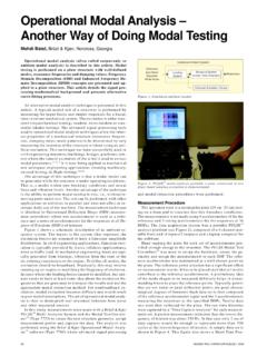
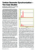
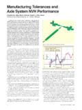
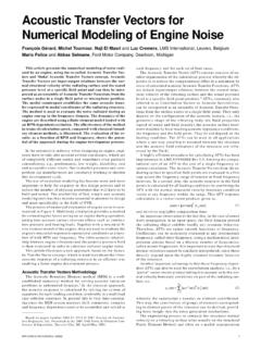
2 The proper-ties of air will cause the front of this Pressure wave to shockup or steepen as the front moves. The result is a shock frontmoving supersonically, , faster that the sound speed of theair ahead of it, with discontinuities in Pressure , density, andparticle velocity across the acoustic waves that move at sonic velocity, produceno finite change in particle velocity, and don t shock up, Air-Blast is a nonlinear process involving nonlinear equations ofmotion. Air-Blast can be encountered in freely expandingshocks in air or, if obstacles enclose the energy source, in di-rected shocks and contained shocks. Examples of all three areshown in Figure near-ideal explosion that is generated by a spherically sym-metric source, and that occurs in a still, homogeneous atmo-sphere, would result in a Pressure -time history similar to theone illustrated in Figure 2. The Pressure is at ambient until theair- blast arrives. At this time it instantaneously rises to its peakside-on overpressure, decays back to ambient, drops to a par-tial vacuum, and eventually returns to from this ideal waveform are to be expected.
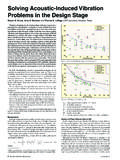
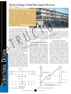
3 Rar-efaction waves occur at the contact surface between the explo-sion products and air; these waves result in modification of thepositive shock caged explosives, any fragment that is generated mayhave an associated momentum adequate for it to outrun theblast-wave velocity and produce disturbances before the wave sarrival. Ground effects due to dust or heat-reflecting surfacesmay form a precursor , if the blast wave has low specific energy, it maytravel a significant distance before shocking up. The inter-action of blast waves with a solid object can result in reflec-tions from the object or cause the waves to reflect from as wellas diffract around the 3 shows the reflection of strong shock waves from areflective surface. I1, I2, and I3 represent the expanding shockwave, while the R contours represent the respective reflectionsfrom the surface. When I1 just touches the surface S, a reflec-tion occurs that is more than two times I1. As the shock wavecontinues to move outward, the intersection of each I and itscorresponding R lies on the dashed line.
4 The incident and re-flected shocks coalesce to form a Mach stem. As the shockexpands, the Mach stem grows, eventually encompassing the2-shock system above the blast wave propagates to greater distances from itssource, its magnitude lessens and it decreases in velocity un-til it propagates at the speed of sound. Theoretically, acousti-cal laws could then apply, but meteorological conditions tendto control its properties at long development of predictive codes and analytical tech-niques for the strength and directional characteristics of blast -waves is highly dependent on experimental blast - Pressure transducers were not always available tomake these measurements; they had to be of the early development of these blast - Pressure trans-ducers occurred at government laboratories such as the Ballis-tic Research Laboratory (BRL United States) and Royal Ar-mament Research and Development Establishment (RARDE United Kingdom) in the 1950s and 1960s. Among the earlycommercial Pressure transducer developers were Atlantic Re-search Corporation, Kaman Nuclear Corporation, Kistler Instru-ment Corporation (where some of its founders subsequentlyformed PCB Piezotronics), and Shaevitz-Bytrex characterize the time signature of a blast - Pressure event,transducers are required for two types of measurements.
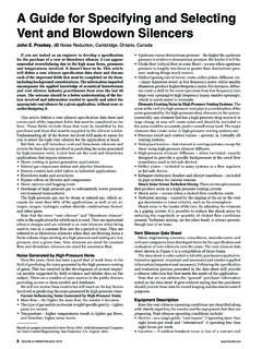
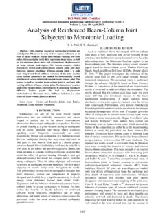
5 Side-on transducers (incident) are those that record free field pres-sure at varying distances from the blast source. Their designmust minimize interference with the flow behind the shockfront. Reflected- Pressure transducers are used for measuringpressures reflected at normal or oblique incidence from a rigidsurface. Flow and diffraction effects are no longer type of transducer must be mounted so that its sensingsurface is flush with the reflecting surface for the shock of the notable pioneers in this field was Mr. Ben Granathwho originally worked at BRL and subsequently foundedSusquehanna Instruments, a development company for blasttransducers. This company is now a part of PCB of two transducers, which resulted from s work, are provided as Figure Figure 4A, the pencil probe, is obviously intended for side-on pressures. Its quartz acceleration compensated piezoelec-tric sensing element is built into the housing. The geometry ofthe contained piezoelectric element, as well as the velocity ofthe shock front of the blast wave passing over it, control its risetime.
6 This transducer covers a Pressure range extending to 1000psi. The transducer in Figure 4B works on the principle of apressure bar. Its sensing element is tourmaline, which is inter-faced to an internal bar. The bar is acoustically impedance-matched to the tourmaline, resulting in a resonantfrequency for the transducer. This model transducer is used forreflected Pressure measurements to 20,000 limitation of the early piezoelectric transducers developedby government labs and/or industry was the influence of thecable on their signal. In hazardous tests, such as those involv-ing explosives, cable lengths of hundreds to thousands of feetare typical. When these cable lengths were employed withcharge-sensing circuits, a variety of deleterious effects wouldresult; the principal problems were:yNoise generated within the cable due to triboelectric high cost of special noise-treated cables to eliminate theabove charge sensing amplifier s noise level, which increases inproportion to cable capacitance, , cable of the aforementioned problems have subsequently beensolved with integral-electronics piezoelectric (IEPE) transduc-ers.
7 PCB Piezotronic s equivalent registered trademark, whichpredates the IEPE designator, is ICP . The IEPE configurationconverts the transducer s output to low impedance, thus elimi-nating triboelectric effects, and it also permits the use of a va- Air-Blast and the Science ofDynamic Pressure MeasurementsPatrick L. Walter, PCB Piezotronics, Depew, New York and Texas Christian University Fort Worth, Texas11 SOUND AND VIBRATION/DECEMBER 2004riety of inexpensive 2-wire cable systems, none of which re-quire noise treatment. In addition, if a typical 20-milliampcurrent is used to power the transducer, the high-frequencyresponse of the transducer is maintained over very long cableruns. Figure 5 shows a cross-sectional view of a vibration com-pensated Pressure transducer in an IEPE or ICP the blast Pressure TransducerOf initial concern in the application of modern transducersto measure Air-Blast phenomena is the interface between theblast Pressure transducer and the measurand (the blast envi-ronment).
8 Figure 4 showed a Model 137A ICP blast pressuretransducer in a pencil probe configuration for side-on pressuremeasurements. In application, its axis must be aligned incident(perpendicular) to the incoming air blast wave. Its size shouldbe small relative to the highest frequency of interest in theshock front. For example, assume a shock front is moving at3,300 feet per second. The wavelength l corresponding to aspectral frequency f of 20,000 Hz in the front would be:Looking at the dimensions of the pencil probe in Figure 6relative to the preceding value of l, it is clear that the probehas the potential to act as a reflecting body to high frequen-cies in the approaching shock order to minimize reflections, the probe is tapered overapproximately its first two-inches of length. It then transitionsinto a cylindrical body with a flat surface on one side. This flatsurface eliminates discontinuities between an embedded, disc-shaped, radial facing, quartz sensing element and the trans-ducer housing.
9 Ideally, the velocity of the shock front and thespatial averaging of the disc as the front traverses across it willcontrol the measured rise time. The averaging effect associatedwith any Pressure transducer can be envisioned as the distor-tion that a sine wave would encounter as it passes at rightangles to the axis of symmetry that is perpendicular to the planeof the circular diaphragm of the transducer. The diaphragmwould cause distortion through spatial averaging of the wave,which results in of the spatial averaging effect of the diaphragm ofpressure transducers has been Results are shownin Figure 7. When using these results, the velocity (in/second)of the gas passing over the transducer must be applied as amultiplier to the abscissa (x-axis) to convert its units to Hz. Asan example of the application of Figure 7, at 1100 ft/sec (13,200in/sec) in dry air, a diameter diaphragm would nomi-nally produce a five-percent amplitude error at 9,200 Hz, anda diameter diaphragm would produce the same error at24,000 reflected pressures at a stationary barrier, the averagingeffects due to flow at normal incidence are not a , the diaphragm of the transducer should be flush withthe reflecting surface.
10 If the diaphragm is flush, the structuralproperties of its sensing element control its Dynamic perfor-mance. However, in some instances, deviations from flushmounting might be deviations could be needed to isolate the transducerfrom high temperature or some other harsh environment. In thissituation, the transducer could be coupled to the process by alength of tubing or other intermediate fitting. The resultantllfc===3300 (12) inches per second 5. ICP vibration compensated Pressure 4: PCB blast Pressure 3. Strong shock wave interaction with a reflective 2. Ideal side-on Pressure record attributable to a spherical sym-metric source in a homogeneous 1. Examples of freely expanding (A), directed (B), and containedair-blasts (C).peak side-on overpressureambient pressurepartial vacuumpositive phasenegative phaseFigure 6. Outline drawing of the Pencil Probe in Figure AND VIBRATION/DECEMBER 2004passageway could even be filled with a porous material of highspecific heat capacity to further reduce the temperature of thegaseous explosion products, thus lessening their effect ontransducer performance.