Transcription of Solving Acoustic-Induced Vibration Problems in the …
1 SOUND & Vibration /AUGUST 2013 Failures of piping in the hydrocarbon industry represent a potential for catastrophic accidents in terms of both lost lives and dollars. It has been reported that more than 20% of the pip-ing failures in the UK sector of the North Sea were due to piping Vibration and fatigue failures. It is clear that Acoustic-Induced Vibration is a serious risk since a single failure will often shut down a facility for hours or days, resulting in lost production at a minimum. In the 1980s, nine AIV failures were documented and used to develop criteria. One resulting criteria system plots the sound power level versus the diameter of the pipe; another plots the sound power level versus the ratio of the nominal diameter to the wall thickness of the pipe. Safe design curves are then drawn through the data. One of the simplified approaches seems to have misinterpreted the original data and now has a safe design curve where a failure has occurred.
2 Since the 1980s, there have been many more failures, but the documentation of these failures has not been shared with the engineering community. This article discusses the existing criteria, presents CSTI s past approach to the challenge of designing to avoid potential AIV Problems , identifies a new failure curve as a function of the ratio of the mean diameter to the thickness squared, and proposes a new safe design 2010, Marsh Energy Practice1 presented a summary of the property damage losses in the hydrocarbon industry. There is no record that any of these losses were actually caused by fatigue due to Acoustic-Induced Vibration (AIV); however, it is highly probable that pipe fatigue was the cause of some losses. The total dollar value of these losses, adjusted for inflation, is greater than billion USD (2009). Tragically, more than 200 people were killed from 1975 to , the Energy Institute discussed the link between pipe fatigue and the release of hydrocarbons from some North Sea platforms:2 Data published by the UK s Health & Safety Executive for the offshore industry have shown that in the UK Sector of the North Sea, piping Vibration and fatigue accounts for over 20% of the hydrocarbon releases.
3 Although overall statistics are not available for onshore facilities, data are available for individual plants that indicate that in Western Europe, between 10% and 15% of pipework failures are caused by Vibration -induced article summarizes an approach to identifying and Solving Acoustic-Induced Vibration Problems in the design stage for the oil and gas devices, such as relief valves, control valves, and orifice plates, can generate high levels of high-frequency acoustical energy downstream of the valve. The sound power level is a function of the pressure drop across the device, the upstream pressure, the mass flow through it, the molecular weight, and the temperature. This acoustical energy propagates downstream of the valve where the resulting Vibration has caused failures due to fatigue, sometimes in just a few hours of sound power level Lw of the valve or orifice plate can be calculated as follows: where:Lw = sound power level in dB re 10 12 wattsM = mass flow in kg/secP1 = upstream pressure in kPa absoluteP2 = downstream pressure in kPa absoluteT = temperature in KelvinW = molecular weightK = zero for nonsonic flow and +6 for sonic flow conditionsHistory of Pipe Failures Due to AIVIn the 1980s, Carucci and Mueller3 (C-M) investigated failures of thin-walled piping.
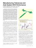
4 They reported nine failures. Their work also lists 27 situations that did not fail. Figure 1 presents the C-M data with the reported Lw plotted as a function of the nominal diameter D. The nine failures are noted with letters A-H, and the 27 non-failures with numbers 1-27. The blue curve is their safe design criteria curve and is valid for non-continuous operation for a total of not more than 12 plotted the C-M data as a function of the ratio of the nominal diameter to the wall thickness D/t rather than D. Although Eisinger indicated in the text that internal diameter was used, the table clearly shows the use of the same nominal diameter as noted by C-M. Also, Eisinger plotted points H and 27 at substantially higher Lw than the original C-M values (perhaps due to calculating the power at the valve rather than at the point of failure). McMa-hon5 has confirmed that point H is plotted correctly in the graph Solving Acoustic-Induced Vibration Problems in the Design StageRobert D.
5 Bruce, Arno S. Bommer and Thomas E. LePage, CSTI acoustics, Houston, TexasBased on a paper presented at Inter-Noise 12, the 41st International Congress & Exposition on Noise Control Engineering, New York, NY, August 1. Carucci and Mueller data and criteria 2. AIV data and criteria **=- + +K(1) SOUND & Vibration /AUGUST 2013 9in the C-M number of oil companies have shared some additional failure and non-failure data, which are plotted in Figure 2 as a function of the nominal diameter divided by the thickness along with the original C-M data. The only information on the new data points is the Lw and the D/t ratio. The black curve is the CSTI design criteria curve: This equation, patterned after C-M and developed by Riegel,6 is shaped to plot below the known failures, which can be attributed to AIV.
6 Point F of the C-M data, a failure at Lw = 165 and D/t = 55, was the result of an undercut weld, which had no further issues after repair. Therefore, it is not an AIV failure, but is more properly at-tributed to construction technique and was ignored for the purpose of fitting the CSTI curve. The new reported failures are labeled I, J, K, and L, and the additional reported non-failures are labeled 28-39. Point L (Lw = 178 and D/t = 31) operated for more than 12 hours and therefore would not be a failure of the criteria Eisinger curve, which has been incorporated into the NORSOK Standard L-002 Edition 3, July 2009, is presented as the straight line in Figure 2. The formula for this line is: where t is the thickness in mm, and Di is identified as the internal diameter, Eisinger seems to have plotted his figures using the nominal diameters. Although it purports to be a safe design curve, there has been at least one failure on this curve, namely point H, which falls on the line when plotted with the original are no AIV failures below the Riegel/C-M curve.
7 Plotting Lw against D/t (rather than against D) continues to serve as the design approach for several major companies, using a criteria curve that is similar to the black curve shown in Figure number of failures at each pipe thickness is summarized in Table 1. For the C-M data, the pipe diameter and thickness are given. For the new data, we have only D/t; neither the diameters nor the thicknesses were specified. Using standard piping size sched-ules, we have evaluated the D/t for each pipe diameter. There are at least two possibilities for diameters and thick-nesses for data points I, J, and K, and three pos-sibilities for data point L. Figure 3 presents all of the data, with the thickness of the pipe identified by the color of the circle, square, or triangle around the data point and with failures indicated by a slash through the circle or square. While we have not seen any reports of failures with pipe walls thicker than inches, this is not proof that pipes will not fail above this thickness.
8 For the four new data points for failures, we have plotted a single value of D/t2, with thicknesses as follows: I inch, J inch, K inch, and L points 28-39, representing the new non-failure data, are more difficult to classify into relevant diameters and thicknesses. For some data points (30, 32, 33, 34, 35, and 37), there are two or more combinations of diameters and thicknesses that give the rel-evant D/t. For data point 28, we could find no possible combination of standard diameter and thickness to give the appropriate D/t. For data points 29, 31, 36, 38, and 39, there is a single diameter and thickness that gives the appropriate D/t. These new data points are coded with the following thicknesses (in inches) in Figure 3: 29 , 30 , 31 , 32 , 33 , 34 , 35 , 36 , 37 , 38 , and 39 Acoustics ApproachValves produce sound power inside the downstream line. The sound is radiated downstream through the piping system and out through the walls of the line, causing the walls to vibrate.
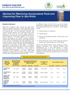
9 Most of the energy stays inside the line with very little attenuation over sections where the sound power level exceeds the criteria, the pipe is vibrating significantly due to the high internal sound power levels. Failure points arise with AIV when there is an asymmetric junction or attachment. The movement of the pipe can cause high stresses at the joint and an eventual failure. For lines with sound power levels above the criteria, the asymmetric discontinuities in the pipe wall are the potential failure points. These include branch connections, tie-backs, support saddles, vents, drains, and any welded connections to the on how much the internal sound power level exceeds the criteria, the piping design is revised depending on established guidelines. Table 2 shows the criteria used at several petrochemi-cal s approach is to calculate the Lw of the valve using Eq. 1 and propagate the sound power down the line, comparing the Lw with the criteria along the line.
10 If the criteria are exceeded, we see if source controls will be allowed, : Use more valves, reducing Lw Use different valves, reducing Lw Use multi-staged restriction orifices, reducing Lw Use an in-line silencer, reducing LwQuiet valves are available and have been used to control AIV. We are unaware of any in-line silencers having been used for AIV Problems and no manufacturers responded to a recent bid request for , we consider the possibility of using damping and stiffener rings. Hayashi et reported reduction of stress by 43% in a finite-Table 1. Pipe wall thicknesses for documented AIV Wall Thickness, InchesTotal C-MFailuresC-M , , C, D, E, G, , L> 3. AIV data from Figure 2, with CSTI curve and pipe wall thicknesses.(3)LDtwi=17360125../Lw= - + --4 2914102 8195100 - +20 (2)Figure 4. Finite-element modeling of stiffener SOUND & Vibration /AUGUST 2013element model that calculated the effect of stiffeners on pipe wall stresses.