Transcription of Turbine Generator Synchronization – Two Case …
1 SOUND & VIBRATION/MAY 2012 This article presents two case studies of increased vibrations as-sociated with load dispatch and removal from gas Turbine -driven synchronous generators during electrical supply Synchronization . The first case involves a classical uneven air gap fault due to a loose foot on the Generator . Such faults are readily detected from the 2 line frequency associated with an electrical defect source. Another case involves unusually high transient vibrations during Synchronization and not widely reported in the literature. Vibra-tion levels increased during Synchronization which, under full load conditions, remained high and resulted in a unit trip due to excessive vibration levels. At partial-load conditions, the high-transient vibrations dropped back down to pre- Synchronization levels.
2 Dominant vibration frequency was at 1 synchronous fre-quency (and not the classical 2 line frequency). This fault was not due to the generators themselves but due to defects involving the Synchronization process with likely out-of-phase Generator sets are used in power generation and are connected within a power grid system typically to the electricity grid on a district or a stand-alone power system such as on an off-shore oil and gas facility. Common vibration problems in Turbine generators often relate to mechanical faults associated with mass unbalance, misalignment and rubs. Problems originating from the Generator are less frequent and can often be misdiagnosed by plant operators and third-party personnel.
3 This article presents two case studies of Turbine Generator vibration problems originating from Synchronization of the Generator with the electrical power system to which the units were dispatching power. Synchronous generators convert mechanical energy from a prime mover (typically a gas or steam Turbine ) to alternating current (AC) electric energy. A direct current (DC) is applied to the rotor winding of a synchronous Generator to produce a rotor magnetic field. The prime mover rotates the Generator rotor to induce a rotat-ing magnetic field in the machine. A three-phase set of voltages is generated in the stator windings by the rotating magnetic field. For electrical power to be dispatched into the electricity grid (which is at a higher electrical potential), the disconnected Generator has to be synchronized into the power network grid.
4 Connecting a synchronous Generator to the power system is a dynamic process, requiring the coordinated operation of many components (elec-trical, mechanical and often human). The goal is to connect the spinning Generator to the system when the Generator matches the system in voltage magnitude, phase angle and Generator and Synchronization FaultsProblems with Turbine generators may be classified as mechani-cal or electrical/electromagnetic in nature. Typical mechanical vibration problems, as in any rotating machine, are mass unbal-ance, misalignment and rotor rubs. Mass unbalance occurs due to imbalance in the rotor assembly (from blades of non-identical mass distribution) and for in-service machines usually from lost parts or foreign object damage (FOD).
5 Such mass unbalance results in high overall vibrations and is easily identified from the increase of the synchronous 1 RPM vibration component in the vibration spectrum as well as from the phase relationships of vibration measured across the Turbine gen-erator set. Misalignment occurs from inadequacies in correct align-ment of the rotors across the coupling. With in-service machines, this is more often induced via pre-loads due to thermal expansion and problems in the supports instead. Alignment-related faults are easily identified from the synchronous 1 RPM and 2 RPM vibration components in the vibration spectrum as well as from the phase relationships of vibration measured across the Turbine Generator set.
6 Rotor rubs and bearing failures are often the result of excessive vibrations from mass unbalance and/or misalignment. Another occasional problem with in service equipment can be from loose mounting problems are associated with unequal air gaps that pull the rotor more strongly at the location of least gap and cracked or broken rotor bars that move and change the rotor balance under the effects of a magnetic field and centrifugal Stator problems, eccentric rotors and phasing problems result in high vibrations at 2 electrical AC frequency (2 line frequency). For synchronous generators this 2 line frequency is also the 2 RPM rotational frequency. Since electrical problems are less frequent, the initial suspect of this 2 synchronous component is a misalignment or preload fault.
7 While an experienced vibration analyst can easily distinguish the mechanical and electrical fault when power is removed, the sequence of events during Synchronization is mea-sured in seconds, and differences in vibration behavior could be easily missed. If the problem is electrical in nature, the excessive vibration and particularly the 2 line frequency component would disappear immediately when power is removed. If the problem is mechanical, the vibration components (2 RPM) would decay in proportion to the speed. An example of this diagnostic process us-ing real-time station DCS (distributed control system) monitoring data and FFT spectrum comparison is presented in case Study less frequent problem relates to faults arising from the Synchronization process.
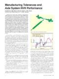
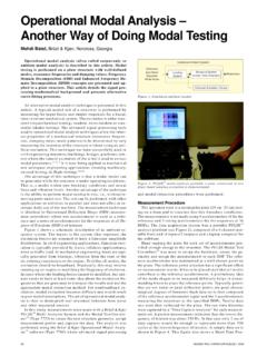
8 Electric power systems consist of an interconnection of multiple units of synchronous generators Turbine Generator Synchronization Two case StudiesM. Salman Leong , Lim Meng Hee, and Guai Yeu KaeUniversiti Teknologi, Kuala Lumpur, MalaysiaFigure 1. Vibration spectrum Generator drive end bearing: (a) with load dispatch; and (b) immediately after power SOUND & VIBRATION/MAY 2012 9operating in parallel. The generators are connected by electrical power transmission cables supplying the power network system. The disconnected Generator can be paralleled when the genera-tor voltage and network voltage are momentarily in phase. The failure of the synchronizing procedure results in an out-of-phase Synchronization .
9 Different causes of this can be due to: Failure in wiring during commissioning and maintenance Delay during breaker closure Flash-over in breaker contact Wrong setting of synchronizing systemExtensive papers have been published related to electrical sta-bility and issues related to voltage instability in power network systems from the perspective of power system dynamics and ,4 A review paper on the phenomena and its problems was for example published by Vibration problems during Synchronization of power generators however have not been widely reported; this is even less so for in-service machines. Chen et reported concerns of loss of life in a Turbine Generator following a faulty Synchronization incident.
10 A unique problem of time-varying vibrations during Synchronization not widely reported in the lit-erature is presented in case Study 1 Classical Behavior This case involved a 100-MW gas Turbine used in a combined-cycle power plant. Rotor speed was 3000 RPM for electrical power generation (50 Hz). Relatively high vibrations were reported for the gas Turbine Generator . The station monitoring sensors showed cas-ing vibration levels on the drive end bearings to be on the order of 7 to mm/s. The Generator nondrive-end bearings had casing vibra-tions in the order of 1 mm/s, and on the Turbine compressor bearing, 3 mm/s. Vibration spectrum showed a high vibration component at 100 Hz (see Figure 1). As condition-based monitoring (CBM) practices usually do not involve phase measurements or correlation of phase relationships across the machine, the 100-Hz vibration component was initially diagnosed as 2 RPM, and a misalignment was immediately suspected by the CBM personnel.