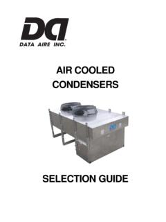
Transcription of Air Cooled Condensers - Data Aire
1 Air Cooled Condensers Installation, Operation and Maintenance Manual This manual is intended to assist trained service personnel providing necessary guidelines for this particular equipment. Service provided for Data aire units is to be done by qualified individuals with an adequate experience and training in HVAC, electrical, plumbing and electronics (as applicable). Service performed by unauthorized or unqualified technicians may void manufac- turer's warranties and could result in property damage and/or personal injury. Special care should be given to those areas where caution symbols appear. Data aire , Inc. reserves the right to make design changes for the purposes of product improvement or to withdraw any design without notice. Table of Contents Installation ..4. Storage ..4. Warranty ..4. Paperwork ..5. Location.
2 5. Vibration ..6. Rigging ..6. Leg Electrical Connections ..7. Electrical Service ..7. Nameplate Ratings ..7. Grounding ..7. Voltage Phase ..7. Wiring Diagrams ..7. Piping ..8. Discharge Lines ..8. Discharge Gas Pulsation ..8. Liquid Lines ..8. Field Piping ..9. Connection Sizes ..9. Leak Testing ..9. Evacuation ..9. Charging ..10. Fan Speed Control/Fan Cycling ..10. Ambient Thermostats ..10. Charging with Fan Speed Control (R-407C) .. 11. Flooded Systems .. 11. Charging Flooded R-410A - Charging/Installation Work Procedures ..12. Refrigerant Handling ..13. Condenser with EC Motor/Fan Blade Combinations ..13. Trouble Shooting Guide (Units with EC motors) ..14. Confirm Incoming Voltage ..15. Checking the Relay Outputs to the Motor ..15. General Note on Control Wiring ..16. Maintenance .. 16. Warranty .. 17. Line Sizing.
3 18-19. Temperature/Pressure Drawings .. 21-24. Contact Data aire , INSTALLATION. There is no intent on the part of Data aire , Inc. to define local codes or statutes which may su- persede common trade practices. Data aire assumes no responsibility for their interpretation. Consult local building codes and the National Electric Code (NEC) for special installation require- ments. Inspection This Data aire unit has been factory run-tested and has gone through a comprehensive inspec- tion prior to its packaging and shipment to ensure that it arrives in excellent condition. However, shipping damage can occur and a visual inspection of the outer crating immediately upon delivery should be performed. Note any external damage or other transportation damage on the freight carrier's forms. Inspect the unit for internal damage. A claim should be filed with the shipping company if the equipment is damaged or incomplete.
4 Loose items such as remote control panels, disconnect switch handles, etc. are packed inside the unit's electrical panel. Freight damage claims are the responsibility of the purchaser. Action to recover losses should be filed immediately. Please notify Data aire traffic personnel of any claims. Storage Data aire equipment comes ready for immediate installation. In some instances it may be nec- essary to store the equipment for a period of time. If you must store the equipment it should be done in a dry area, out of the weather, protected from freezing weather, protected from damage by other equipment in storage or transportation equipment, never stacked (if uncrated). Avoid frequent relocation. If equipment is stored more than 30 days special precautions must be taken to avoid coil damage. All coils should be charged and sealed with a low pressure (1-3 PSIG) inert gas, such as nitrogen.
5 This prevents contaminates from entering the coil(s). When the seal is broken at installation, the rush of escaping gas verifies the coil is still leak free. If coils are not charged and sealed conden- sation mixes with air pollutants forming a weak acid and over time can cause pin hole leaks to develop in the coil tubes. When equipment is installed after storage caution should be taken to inspect and replace parts. All moving parts, such as blowers and motors, should be hand tested to ensure they are free and prior to start-up. Warranty This equipment is designed to operate properly and produce rated capacities when installed in accordance with accepted industry standards. Failure to do so could result in voiding the system warranty. The following conditions should be met: 1. System piping must be installed following accepted industry practices 2.
6 Inert gas must be charged into piping during brazing 3. System must be thoroughly leak checked and evacuated before charging (using a high vacuum gauge capable of reading microns). 4. 4. Power supply requirements to the system (Section ). 5. All control and safety switch circuits must be properly connected per unit wiring diagram 6. Factory installed wiring can only be changed with written factory approval Paperwork It is the responsibility of the installing contractor to return the start-up and warranty registration card to Data aire for proper activation of the unit warranty. Failure to do so may cause delays and in some cases void the warranty. WARNING: This equipment may contain substance that has been deemed harmful to public health and the environment. Venting of refrigerants to the atmosphere is illegal. Refrigerant recovery devices must be used when installing and/or servicing these types of products.
7 Locating the remote heat exchanger Air Cooled Condensers should be located in secure areas where service is easily accessible. Areas where public access is available should be avoided. Avoid areas that contribute to ice and snow accumulation. Condensers should be located in clean areas free from debris or foreign mat- ter that could block the coil surface. Avoid areas of hot air or fume exhaust. Condensers should not be located near steam vents. Condensers should not be closer than 36 inches from a wall or any obstruction. With proper clearance on all other sides units can be placed side by side. Additional units should be placed no closer than 48 inches apart. Avoid air recirculation conditions that could be caused by walls, screening, etc. Do not connect ductwork to the coil inlet or fan outlet. Keep fan discharge away from building air intakes.
8 The remote heat exchanger must be located in an area that will ensure airflow into and out of the heat exchanger plus adequate service access clearance. Short circuiting of the airflow or the in- take of warmer air from another unit will seriously degrade the performance of the air Cooled heat exchanger. Do not locate the heat exchanger in a location that is bordered by tall obstructions ( higher than 10 feet) on no more that two sides. See figure on page 21 for minimum clearance from obstruc- tions and between units. With proper clearance on all sides, two units can be placed side by side. Additional units should be placed at least 48 inches apart. Noise factors should be considered when locating an air Cooled heat exchanger. Proximity to windows, walls and surrounding structures can cause objections by the occupants.
9 An acoustical expert should be consulted when noise is of a particular concern. Air Cooled Condensers should be placed at a level that is higher than the indoor evaporator. Mounting the remote heat exchanger more than 10 feet below the evaporator is not recommend- ed. Excessive liquid line pressure drop can cause poor evaporator performance. Piping must be supported within 18 inches of the inlet and outlet connections. The inlet connec- tion is located on the top header on all remote heat exchangers and the outlet connection is lo- cated on the bottom header of all units. 5. Vibration Avoid installing units near occupied spaces, above or outside utility spaces and corridors when- ever possible in order to reduce sound transmission and/or vibration to occupied spaces. Refrig- erant piping should be flexible enough to prevent transmission noise or vibration from the unit.
10 Isolation hangers should be used to prevent the transmission of vibration on all suspended (from the building) refrigerant lines. Rigging The heat exchanger should be moved to its mounting location (typically rooftop) using a crane or fork lift. Each fan section has heavy steel leg supports with lifting holes at the top. Do not lift with a choke sling around the unit. Spreader bars are recommended for lifting multiple fan units. Under no circumstances should the coil headers or piping be used for lifting the unit. The unit should be kept in the shipping crate until it is ready to be set in place. Leg Assembly The legs must be unbolted from their collapsed shipping position and extended prior to placing the unit on its pad. Each leg extends down 18 inches and reattaches using the same nuts and bolts. Failure to extend the legs will result in improper air distribution over the condenser coil resulting in significant performance loss.
