Transcription of Aloyco Corrosion Resistant Valves - AIV, Inc.
1 The First Name In Corrosion Resistant ValvesAloyco Corrosion Resistant ValvesT: 562-426-2531 F: 562-490-9546 Figure No. Valve Type Pressure Class End Connection Material Available Size Range Catalog Page 90 Gate, RS 200 CWP Threaded CF8M 1 2" - 2" 5 190 Gate, NRS 200 CWP Threaded CF8M 1 2" - 2" 5 110 Gate, OS&Y 150 Threaded CF3M 1 2" - 2" 6 114 Gate, OS&Y 150 Socket Weld CF3M 1 2" - 2" 6 117, 117F Gate, OS&Y 150 Flanged CF8M 1 2" - 24" 7 2110 Gate, OS&Y 300 Threaded CF3M 1 2" - 2" 8 2114 Gate, OS&Y 300 Socket Weld CF3M 1 2" - 2" 8 2117, 2117F Gate, OS&Y 300 Flanged CF8M 1 2" - 24" 9 4210 Gate, OS&Y 600 Threaded CF3M 1 2" - 2" 10 4214 Gate, OS&Y 600 Socket Weld CF3M 1 2" - 2" 10 4117 Gate, OS&Y 600 Flanged CF8M 2" - 12" 11 40 Globe 200 CWP Threaded CF8M 1 2" - 2" 12 310 Globe 150 Threaded CF3M 1 2" - 2" 13 314 Globe 150 Socket Weld CF3M 1 2" - 2" 13 317 Globe 150 Flanged CF8M 1 2" - 12" 14 2310 Globe 300 Threaded CF3M 1 2" - 2" 15 2314 Globe 300 Socket Weld CF3M 1 2" - 2" 15 2317 Globe 300 Flanged CF8M 1 2" - 8" 16 4310 Globe 600 Threaded CF3M 1 2" - 2" 17 4314 Globe 600 Socket Weld CF3M 1 2" - 2" 17 4317 Globe 600 Flanged CF8M 1 2" - 6" 18 49 Swing Check 200 CWP Threaded CF8M 1 2" - 2" 19 370 Swing Check 150 Threaded CF3M 1 2" - 2" 20 374 Swing Check 150 Socket Weld CF3M 1 2" - 2" 20 377 Swing Check 150 Flanged CF8M 1 2" - 24" 21 2370 Swing Check 300 Threaded CF3M 1 2" - 2" 22 2374 Swing Check 300 Socket Weld CF3M 1 2" - 2" 22 2377 Swing Check 300 Flanged CF8M 1 2" - 24" 23 4370 Swing Check 600 Threaded CF3M 1 2" - 2" 24 4374 Swing Check 600 Socket Weld CF3M 1 2"
2 - 2" 24 4377 Swing Check 600 Flanged CF8M 1 2" - 12" 25 9431-S-LL Ball - 2 pc 2000 CWP Threaded CF8M 1 4" - 2" 26 Stainless Steel ValvesGeneral IndexT: 256-775-3800 F: 256-775-3860 : 256-775-3800 F: 256-775-3860 to Specify and Order the Correct ValvesThis catalog has been published to assist you in choosing the correct valve for a vast number of piping conditions. The Aloyco product line makes available to you a very broad choice of Valves . These Valves are described in this should be taken to select the most suitable Valves for your service(s). Exact specification of each valve should be made to avoid possible ambiguity. When requesting quota-tions and/or ordering the product a fully adequate description should be the Valve SizeNominal size of the pipeline into which the valve will be placed must be MaterialThe following facts should be considered in determining the correct valve material: the medium or media which will be controlled the temperature range of the line medium (media) the pressure range to which the valve will be subjected possible atmospheric conditions which may affect the valve possible extraordinary stresses to which the valve will be subjected safety standards and/or piping codes which must be metType of ValveWhat is the control function of the valve?
3 Each valve con-figuration has been developed to perform certain control functions. Do not expect one type of valve to perform all the valving jobs in a RatingsPlease pay careful attention that the pressure-temperature ratings of a particular valve are in keeping with the require-ments of the service. Pay especially careful attention to the packing and gasket materials as this may limit the rating as is the case with PTFE used as the standard in Aloyco Valves . We offer graphite packing and gaskets in many sizes and pressure classes. Specify graphite or alternative packing and/or gasket materials as necessary to meet or exceed your service To OrderStainless Steel ValvesValve and ConnectionsConsiderations as to pipeline integrity, future maintenance, Corrosion factors, field assembly, weight and safety should be given in determining the method of connecting the valve in the of OperationThe means by which the valve is operated as supplied are shown for the Valves in this catalog.
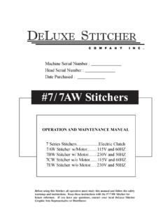
4 Many optional operating devices are regularly supplied by the ValvePlease state the following information when ordering a valve in order to avoid unnecessary delays and to insure we supply you with the valve you have Valve Pressure boundary material - metallurgy of the castings and Type of valve - gate, globe, check, End connection including wall thickness of connecting pipe if weld end and any special flange facings or Any material deviations from standard - packing, gasket, bolting, Any accessories - acid shield, locking devices, chain opera-tion, Manual or power actuators, please include details of For convenience in ordering, specify by figure Aloyco for additional assistance in valve to our policy of continuous product improvement, Aloyco reserves the right to change designs, materials, or specifications without : 562-426-2531 F: 562-490-9546 and Weights Dimensions (inches) Valve Weight (lbs) A B (open) C Size 90 190 90 190 90 190 90 190 1 1 2 CWP Threaded Bonnet Solid Wedge DiscFigure 90 Rising StemFigure 190 Non-Rising StemSize Range: through 2 inchesDesign Features: Threaded Ends Integral Seat Figure 190 - Inside Screw/Non-rising StemPressure Temperature Ratings:200 psi @ -20 to 100 F135 psi @ 500 FIndustry Standards Threaded Ends ASME End-to-End Manufacturer's StandardFig.
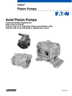
5 90 Stainless Steel Gate ValvesFIGURES90 190 Materials of Construction 1 Body ASTM A351 CF8M 2 Bonnet ASTM A351 CF8M 3 Disc ASTM A351 CF8M 4 Stem 316 SS 5 Packing PTFE 6 Gland 316 SS 7 Gland Nut ASTM A351 CF8M 8 Packing Washer 316 SS 9 Gasket PTFE 10 Handwheel ASTM A536 11 Handwheel Nut 304 SS 12 ID Tag AluminumBA(APPROX)DIAC248591367121011BA( APPROX)DIAC248591367121011T: 256-775-3800 F: 256-775-3860 Steel Gate ValvesFigure 110 Threaded EndsFigure 114 Socket Weld EndsSize Range: through 2 inchesDesign Features: Bolted Bonnet Rising Stem Integral Seat Retained Gasket MSS SP-42 API 603 (except for end connections)Industry Standards Pipe Threads ASME Wall Section ASME Socket Weld Ends ASME End-to-End Manufacturer's Standard Pressure-Temp Rating ASME Testing API 598 Materials of Construction 1 Body ASTM A351 CF3M 2 Bonnet ASTM A351 CF8M 3 Disc ASTM A351 CF8M 4 Stem ASTM A276 T316 5 Handwheel ASTM A536 6 Gasket PTFE 7 Gland Flange ASTM A351 CF8 8 Gland ASTM A276 T304 9 Packing PTFE 10 Stem Nut ASTM A536 11 Handwheel Nut ASTM A276 T304 12 Bonnet Bolt Nut ASTM A194 GR 8 13 Bonnet Bolt ASTM A193 GR B8 14 Eyebolt Pin ASTM A276 T304 15 Eyebolt ASTM A193 GR B8 16 Eyebolt Nut ASTM A194 GR 8 17 ID Tag Aluminum 18 Washer ASTM A536 19 Grease Fitting 304 SS 20 Set Screw SteelFIGURES110 114 Class 150 OS&Y Solid Wedge Disc31BA(APPROX)
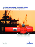
6 DIAC12139201181410194615716218517 Fig. 110 Dimensions and Weights Valve Dimensions (inches) Size Weight (lbs) A B (open) C D* .38 .50 1 .50 1 .50 2 .62*For Figure 114 only - Socket weld depthT: 562-426-2531 F: 562-490-9546 150 OS&Y Solid or Flexible Wedge DiscStainless Steel Gate ValvesFigure 117 Raised Face, Flanged Ends, Solid Wedge DiscFigure 117 FRaised Face, Flanged Ends, Flexible Wedge DiscSize Range: through 24 inchesDesign Features: Bolted Bonnet Rising Stem Integral Seat Retained Gasket MSS SP-42 API 603 Industry Standards End Flanges ASME Wall Section ASME Face-to-Face ASME Pressure-Temp Ratings ASME Design API 603 Testing API 598 FIGURES117 117 FMaterials of Construction 1 Body ASTM A351 CF8M 2 Bonnet ASTM A351 CF8M 3 Disc ASTM A351 CF8M 4 Stem ASTM A276 T316 5 Handwheel ASTM A536 6 Gasket PTFE 7 Gland Flange ASTM A351 CF8 8 Gland ASTM A276 T304 9 Packing PTFE 10 Stem Nut ASTM A536 11 Handwheel Nut ASTM A276 T304 12 Bonnet Bolt Nut ASTM A194 GR 8 13 Bonnet Bolt ASTM A193 GR B8 14 Eyebolt Pin ASTM A276 T304 15 Eyebolt ASTM A193 GR B8 16 Eyebolt Nut ASTM A194 GR 8 17 ID Tag Aluminum 18 Washer ASTM A536 19 Grease Fitting 304 SS 20 Set Screw Steel31B(APPROX)DIACA1213920118141019461 5716218517 Fig.
7 117 Dimensions and Weights Valve Dimensions (inches) Size Weight (lbs) A B (open) C 1 1 2 2 3 4 6 8 10 12 14 16 18 20 24 : 256-775-3800 F: 256-775-3860 300 OS&Y Solid Wedge DiscStainless Steel Gate ValvesFigure 2110 Threaded EndsFigure 2114 Socket Weld EndsSize Range: through 2 inchesDesign Features: Bolted Bonnet Retained Gasket Rising Stem Integral Seat MSS SP-42 ASME Standards Pipe Threads ASME Wall Section ASME Socket Weld Ends ASME End-to-End Manufacturer's Standard Pressure-Temp. Rating ASME Testing API 598 Materials of Construction 1 Body ASTM A351 CF3M 2 Bonnet ASTM A351 CF8M 3 Disc ASTM A351 CF8M 4 Stem ASTM A276 T316 5 Handwheel ASTM A536 6 Gasket PTFE 7 Gland Flange ASTM A351 CF8 8 Gland ASTM A276 T304 9 Packing PTFE 10 Stem Nut ASTM A536 11 Handwheel Nut ASTM A276 T304 12 Bonnet Bolt Nut ASTM A194 GR 8 13 Bonnet Bolt ASTM A193 GR B8 14 Eyebolt Pin ASTM A276 T304 15 Eyebolt ASTM A193 GR B8 16 Eyebolt Nut ASTM A194 GR 8 17 ID Tag Aluminum 18 Washer ASTM A536 19 Grease Fitting 304 SS 20 Set Screw SteelFIGURES2110 211431BA(APPROX)DIAC12139112081419461571 618517210 Fig.
8 2110 Dimensions and Weights Valve Dimensions (inches) Size Weight (lbs) A B (open) C D* .38 .50 1 .50 1 .50 2 .62*For Figure 2114 only - Socket weld depthT: 562-426-2531 F: 562-490-9546 300 OS&Y Solid or Flexible Wedge DiscStainless Steel Gate ValvesFigure 2117 Raised Face, Flanged Ends, Solid Wedge DiscFigure 2117 FRaised Face, Flanged Ends, Flexible Wedge DiscSize Range: through 24 inchesDesign Features: Bolted Bonnet Retained Gasket Rising Stem Integral Seat MSS SP-42 ASME Standards End Flanges ASME Wall Section ASME Face-to-Face ASME Pressure-Temp. Ratings ASME Testing API 598 Dimensions and Weights Valve Dimensions (inches) Size Weight (lbs) A B (open) C -- -- 1 -- 1 -- 2 -- 2 3 4 6 8 10 12 14 16 18 20 24 2117 FMaterials of Construction 1 Body ASTM A351 CF8M 2 Bonnet ASTM A351 CF8M 3 Disc ASTM A351 CF8M 4 Stem ASTM A276 T316 5 Handwheel ASTM A536 6 Gasket PTFE 7 Gland Flange ASTM A351 CF8 8 Gland ASTM A276 T304 9 Packing PTFE 10 Stem Nut ASTM A536 11 Handwheel Nut ASTM A276 T304 12 Bonnet Bolt Nut ASTM A194 GR 8 13 Bonnet Bolt ASTM A193 GR B8 14 Eyebolt Pin ASTM A276 T304 15 Eyebolt ASTM A193 GR B8 16 Eyebolt Nut ASTM A194 GR 8 17 ID Tag Aluminum 18 Washer ASTM A536 19 Grease Fitting 304 SS 20 Set Screw Steel31BA(APPROX)
9 DIAC12139112081419461571618517210 Fig. 2117T: 256-775-3800 F: 256-775-3860 600 OS&Y Solid Wedge DiscStainless Steel Gate ValvesFigure 4210 Threaded EndsFigure 4214 Socket Weld EndsSize Range: through 2 inchesDesign Features: Bolted Bonnet Retained Gasket Rising Stem Integral Seat ASME Standards Pipe Threads ASME Wall Section ASME Socket Weld Ends ASME End-to-End Manufacturer's Standards Pressure-Temp Rating ASME Testing API 598 FIGURES4210 4214 Materials of Construction 1 Body ASTM A351 CF3M 2 Bonnet ASTM A351 CF8M 3 Disc ASTM A351 CF8M 4 Stem ASTM A351 CF8M 5 Handwheel ASTM A536 6 Gasket PTFE 7 Gland Flange ASTM A351 CF8 8 Gland ASTM A276 T304 9 Packing PTFE 10 Stem Nut ASTM A536 11 Handwheel Nut ASTM A276 T304 12 Bonnet Bolt Nut ASTM A194 GR 8 13 Bonnet Bolt ASTM A193 GR B8 14 Eyebolt Pin ASTM A276 T304 15 Eyebolt ASTM A193 GR B8 16 Eyebolt Nut ASTM A194 GR 8 17 ID Tag Aluminum 18 Washer ASTM A536 19 Grease Fitting 304 SS 20 Set Screw Steel31BA(APPROX)DIAC1213911208141946157 1618517210 Fig.
10 4210 Dimensions and Weights Valve Dimensions (inches) Size Weight (lbs) A B (open) C D* .38 .50 1 .50 1 .50 2 .62*For Figure 4214 only - Socket weld depthT: 562-426-2531 F: 562-490-9546 600 OS&Y Flexible Wedge DiscStainless Steel Gate ValvesFigure 41172 to 12 inches, Raised Face, Flanged EndsSize Range:2 through 12 inchesDesign Features: Bolted Bonnet Inside Screw Rising Stem Integral Seat Tested to API 598 ASME 4117 Dimensions and Weights Valve Dimensions (inches) Size Weight (lbs) A B (open) C 2 --- 2 3 4 6 8 10 12 Standards End Flanges ASME Wall Section ASME Face-to-Face ASME Pressure-Temp. Ratings ASME Testing API 598 Materials of Construction 1 Body ASTM A351 CF8M 2 Disc ASTM A351 CF8M + STL 3 Stem ASTM A182 F316 4 Body Nut ASTM A194 8M 5 Body Bolt ASTM A193 B8M 6 Ring Gasket ASTM A182 F316 7 Bonnet ASTM A351 CF8M 8 Packing Graphite 9 Gland Bolt ASTM A193 B8M 10 Gland ASTM A182 F316 11 Gland Flange ASTM A351 CF8M 12 Gland Nut ASTM A194 8M 13 Yoke ASTM A351 CF8M 14 Yoke Nut ASTM A439-D2 15 Handwheel Ductile Iron AB (APPROX)C (DIA)T: 256-775-3800 F: 256-775-3860 and Weights Valve Dimensions (inches) Size Weig