Transcription of Axial Piston Pumps - Hydraulics
1 And Variable DisplacementPFB 5, PFB 10, PFB 20 PVB 5/6, PVB 10/15, PVB 20/29, PVB 45 and PVB 90 to SAEPVB 5/6, PVB 10/15, PVB 20/29 to DIN/ISO 3019, Part 2GB-2379 BAxial Piston Pumps Vickers Piston .. General .. Functional .. Model .. Operating .. Minimum Inlet Pressure .. Performance data @ 1500 r/min drive speed:PFB5, PFB10, .. PVB5, PVB6, .. PVB15, PVB20, .. PVB45, .. Performance data @ 1800 r/min drive speed:PFB5, PFB10, .. PVB5, PVB6, .. PVB15, PVB20, .. PVB45, .. Control data for PVB .. Noise .. Installation dataPFB5 SAE flange .. PFB10 SAE flange .. PFB20 SAE flange.
2 PVB5/6 SAE flange mounting C & CM pressure compensator .. PVB5/6 side ported thru .. PVB10/15 SAE flange mounting C & CM pressure compensator .. PVB10/15 side ported thru .. PVB5/6 & PVB10/15 M lever control, & H handwheel .. PVB20/29 SAE flange mounting C & CM pressure compensator .. PVB20/29 side ported thru .. PVB45 flanged .. PVB45 foot .. PVB5/6, PVB10/15 & PVB20/29 CC & CMC pressure compensator and adjustable maximum displacement .. PVB5 29 CG Remote control compensator, CVP Load sensing & S30 drain port option .. PVB5/6, PVB10/15, PVB20/29 DIN/ISO .. Installation.
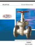
3 CharacteristicsTypeAxial Piston Pumps .. Operating pressureup to 210 bar.. (3000 psi)Displacement10,5 to 197,5 cm3/r.. ( to 12 in3/r)Drive speedup to 3600 r/min.. General DescriptionBoth fixed and variable displacementmodels make up this range of axialpiston Pumps . Their high performanceratings and efficiencies are achievedwith a variety of hydraulic fluids. Fixeddisplacement models are noted for theirvolumetric and mechanical displacement models canclosely match pressure and/or flowdemand with a control selected from: Pressure compensator with or without a remote control facility. Pressure compensator with adjustable displacement control.
4 Load sensing compensator. Mechanical (lever) control. Handwheel controlTypical SectionVariable displacement model with compensator control C or CM Functional SymbolsPFBF ixed displacementmodelsWith handwheel,or pressurecompensator (C or CM)(simplified symbol)With CVP load sensingand pressure limiterPVBV ariable displacementmodelsWith pressure compensatorarranged for remote controlC(M)G (detailed symbol) CodesBasic modelsF= Fixed displacement typeV= Variable displacement typeDisplacementPFB and PVB models:5 = 10,55 cm3/r ( in3/r)10 = 21,10 cm3/r ( in3/r)20 = 42,80 cm3/r ( in3/r)PVB models only.
5 6 = 13,81 cm3/r ( in3/r)15 = 33,00 cm3/r ( in3/r)29 = 61,60 cm3/r ( in3/r)45 = 94,50 cm3/r ( in3/r)90 = 197,50 cm3/r ( in3/r)Foot mounting optionF = Foot mounting option for PVB45 andPVB90 for flange For foot mounting brackets. forother models see bottom of flange M = Metric, to DIN/ISO 3019, Part 2 and VDMA 24560, Part 1 Omit for SAE mounting flangeShaft rotationViewed at shaft endR= ClockwiseL= Anticlockwise (not avalable for PFB10 and PFB20)Displacement zonePVB models One side of center (pressure compensated models only)D= Both sides of center (Handwheel and lever controlled models only)Omit for PFB main portsF= PVB45 and PVB90 models for P*B5 to 29 shaft optionPVB5 to 29 only.
6 X= Thru shaft (with side entry ports)Omit for PVB45 and PVB 90, or if ** (F) (M) *(C)-(G) (L)132414511234567*B-*67(*)8-**9-**10--1 2-13- ** - **16 Shaft typeN= Metric, to DIN/ISO 3019, Part 2 and VDMA 24560, Part 1Y= SAE models P*B5 to 15 for 20 thru 90 modelsPump design number10 = PFB2030 = PFB1031 = PVB10 and PVB1520 = all other modelsDisplacement control optionsPVB models Pressure compensator. Pressureadjustment range:PVB90: 19 to 210 bar (275 to 3000 psi)All other models: 17 to 210 bar (250 to 3000 psi)Also used as prefix for itemNote. For PVB6, 15 and 29 models, theuser must ensure that the max.
7 Pressuresetting never exceeds 140 or 100 bar(2000 or 1500 psi) dependent on thetype of fluid being = Pressure compensator. Option for all sizes except adjustment range:PVB45: 10 to 100 bar (150 to 1500 psi)All other sizes: (17 to 100 bar (250 to 1500 psi)CVP = Load sensing with pressure to 15 only:H= Handwheel controlM= Lever controlV= No control (As for M type but without lever.)Omit for PFB displacementadjustmentPVB5 to 29 models only:C= C or CM compensator, and with Omit when not compensator variationsPVB5 to 29 models only:G= Remotely adjustable pressure when not locationPVB5 to 15 models with H , M or V controls only:L= Left hand, when viewed at shaft for right hand, or when a pressurecompensator is design numberPVB models = H and M controls;also C control for PVB9011 = C and CM = CVP = CG design optionsFor PFB5 and PVB5 to 29 only.)
8 = Extra drain port to permit vertical shaft-up PVB5 to PVB29 pressurecompensated models only:GE1 = 10% minimum displacement. when pressure all models:GEVS= Pressure setting knob with key when not bracket mounting kitsOrder separately if required. Kits includepump fixing pump sizes:code numberFB-A-10 422582 P*B5/6FB-B-10 422583 P*B10/15 and PFB20FB-C-10 422584 PVB20/29121213141516(F)8(X) DataPressure and Speed LimitsBasic modelGeometricMaximum shaftMaximum outletdesignationdispalcement,speed (r/min)pressure, bar (psi)cm3/r (in3/r) Anti-wearWater-in Water-Anti wearWater Water-in hydraulicoilglycolhydraulicglycoloiloile mulsionoilemulsion(40%/60%)(40%/60%)PFB5 10,55 ( )3600210 (3000)PFB1021,10 ( )320018001800210 (3000)175 (2500)175 (2500)PFB2042,80 ( )2400175(2500)PVB510,55 ( )210 (3000)140 (2000)140 (2000)PVB613,81 ( )140 (2000)100 (1500)100 (1500)
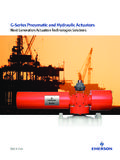
9 PVB1021,10 ( )210 (3000)140 (2000)140 (2000)PVB1533,00 ( )180018001800140 (2000)100 (1500)100 (1500)PVB2042,80 ( )210 (3000)140 (2000)140 (2000)PVB2961,60 ( )140 (2000)100 (1500)100 (1500)PVB4594,50 ( )210 (3000)140 (2000)140 (2000)PVB90197,50 ( )180012001200210 (3000)140 (2000)140 (2000)Maximum Inlet PressureAll Pumps except PVB5/6/10/15 with H, M or V controls1,0 bar (15 psi).. PVB5/6/10/15 with H, M or V controlsAs Max. outlet pressure above.. for appropriate Drain PressureSee Installation data section, on page Inlet PressureSee following on oil viscosity of 21 cSt (102 SUS) and at 50 C (120 F).
10 0,60,81,01,21,41,61,8barpsi1020301525 Absolute pressureSupercharge pressure0,60,8bar0,20,401200240018003600 3000 Drive speed, r/minPFB5 and PVB5psi1005 Vacuum:170 m bar(5 Hg)60000,60,81,01,21,41,61,8barpsi102030 1525 Absolute pressureSupercharge pressure0,60,8bar0,20,401200240018003200 3000 Drive speed, r/minpsi1005 Vacuum:170 m bar(5 Hg) Data Minimum Inlet Pressure (cont d)0,60,82,01,01,21,41,61,8barpsi10203015 25 Absolute pressureSupercharge pressure0,60,81,0bar0,20,403000 Drive speed, r/minPVB15psi101505 Vacuum:170 m bar(5 Hg)0,60,81,01,21,41,61,8barpsi1020301525 Absolute pressureSupercharge pressure0,60,8bar0,20,402000280024003200 Drive speed, r/minPFB10 and PVB10psi1005 Vacuum:170 m bar(5 Hg)0,60,81,01,21,41,61,8barpsi10201525 Absolute pressureSupercharge pressure0,60,8bar0,20,400600120018002400 Drive speed, r/minPFB20psi1005 Vacuum:170 m bar(5 Hg)00,60,82,01,01,21,41,61,82,22,42,6bar psi10203040152535 Absolute pressureSupercharge pressure0,60,81,01,21,41,6bar0,20,400160 020002400 Drive speed, r/minPVB20 and PVB29psi1020152505 Vacuum.