Transcription of AMERICAN Engineering Data
1 SECTION 17 AMERICANE ngineering Data17-1 Energy Savings With Ductile Iron Pipe ..17-2 Present Value of Money ..17-3 Flow of Water in Ductile Iron Pipe ..17-4 Flow of Water in Ductile Iron Pipe (Table 17-1) ..17-5 - 17-8 Gravity Flow in Pipe Manning Formula (Fig. 17-1) ..17-9 Equivalent Pipe Diameters (Table 17-2)..17-10 Equivalent Number of Pipelines (Table 17-3) ..17-11 Diameters, Circumferences, Areas and Volumes for Standard MinimumPressure Classes of Ductile Iron Cement-Lined Pipe (Table 17-4) ..17-12 Weights for Pipeline Design, Weights of Ductile Iron Pipe andContained Water (Table 17-5).
2 17-12 Axial Bulkhead or Dead-End Thrust Due to Pressure (Table 17-6)..17-13 Standard Abbreviations and Acronyms (Table 17-7) ..17-14 - 17-20 Taps in Ductile Iron Pipe - Minimum Distances (Table 17-8) ..17-21 Standard Pipe Taps - Outside Diameters (Table 17-9) ..17-21 Taps in Ductile Iron Pipe - ANSI/ASME (Table 17-10)..17-22 Taps in Ductile Iron Pipe - AWWA C800 Standard (Table 17-11) ..17-23 Linear Expansion of Ductile Iron Pipe (Table 17-12) ..17-24 Pipe Length Calculations for Offset Connections (Table 17-13)..17-25 Pipe Length Calculations for Inclined Diagonal Formulas.
3 17-27 - 17-29 AMERICAN s Standard Color of an Inch and of a Foot (Table 17-14) ..17-31 Equivalents and Conversion Factors - English (Table 17-15) ..17-32, 33 Equivalents and Conversion Factors - Metric (Table 17-16) ..17-34, 35 Section 17 - Engineering DataTable of ContentsEnergy Savings With Ductile Iron PipeAll sizes of standard thicknesscement-lined ductile iron pipe in minimumpressure classes and all special thicknessclasses through Special Thickness Class 52in 4"-54" sizes have greater than nominalinside diameters. Head losses in pipingare directly related to inside diameters,and energy consumption and accompanyingpumping costs are directly related tohead losses.
4 Therefore, the use of ductileiron piping having inside diametersgreater than nominal can result insignificant energy savings over the addition to helping to keep operatingcosts and utility rates reasonable, thisconservation of energy is also helpful tothe environment. Graphs and tables pertaining to thiscan be found in Manual For Compu-tation of Energy Savings With DuctileIron Pipe published by the Ductile IronPipe Research Association (DIPRA).Formulas for calculating pumping costsare as follows:PC = HLQ aEwhere: PC = Pumping cost in $/Year/ 1000 ft of pipe based on 24 Pump OperationHL= Hydraulic Gradient or Head Loss in ft/1000 = Flow in Gallons/Minute (GPM)a = Unit Cost of Electricity in $/KWHE = Total Efficiency of Pump System (pump, motor, transmission always a number less than one)and:HL* = 1000 V (r).
5 V = Velocity in ft/sec (fps)C = hazen - williams c Factor (140 for ductile iron pipe)**r = Hydraulic Radius in ft (inside diameter in ft 4 for pipe flowing full)and:V* = Q :Q = Flow in Gallons/Minute (GPM)A = Cross sectional area of pipe in ft2and:A** = d24where:d** = Inside diameter in ft*See Table No. 17-1 for values of HLand V for standardminimum pressure class cement-lined ductile iron pipe.**The hazen -Williams flow coefficient C=140 has beenused for cement-lined cast iron and ductile iron pipe formany years. The quality of recent, high-performancecement linings for ductile iron pipe, smooth proprietarylinings, and the availability of even larger pipe sizes mayjustify the use of significantly higher values for C.
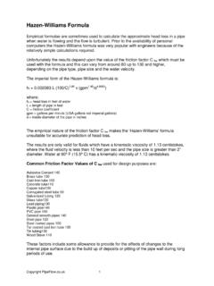
6 This maybe particularly applicable to the intermediate and largerpipe sizes in clean water service. (See pg 17-4.)**See Table No. 17-4 for values of A and d for standardminimum pressure class cement-lined ductile iron pipe.[]17-217-3 Present Value of MoneyThe present value of moneycompounded annually at a giveninvestment rate and an assumed inflationrate over a given period can be calculatedby the following formulas:PV = (1 + i)n- 1i(1 + i)nwhere:PV = Present Value per $1i = Effective interest rate (%/100)n = Number of compounding periods(years)and i = j - i 1 + i where:j = Investment rate (%/100)i = Inflation rate (%/100)Example:Given:50,000' 36" Pressure Class 150 pipe Design flow 14,000 GPMUnit Power Cost $.
7 05 KWHPump Operation 24 Hrs/DayPump System Efficiency 70% hazen - williams c Factor 140 Using the Pumping Cost formula onpage 17-2, Pressure Class 150, cement-lined, ductile iron pipe will saveapproximately $18,075/year in PumpingCosts over a substitute material pipe witha nominal inside Present Value of the $18,075annual savings, over a 50-year timeperiod, and assuming an investment rateof 8% and an inflation rate of 4%, is$397,650 ($18,075 x 22).17-4 The carrying capacity of a givenpipeline is limited by its internal resistanceto the flow of water.
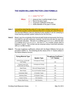
8 This resistance toflow causes a loss of head or drop inpressure as the water moves through theline. The amount of head loss depends on(1) the velocity of the water, (2) theroughness of the interior surface of thepipe, (3) the internal diameter, and (4) thelength of the line. These factors havebeen related in the widely used hazen -Williams formula for computing headlosses, pipe sizes and carrying capacities indistribution lines. This formula is asfollows:V=C x whichV=velocity of water through thepipe in feet per secondC=factor depending on the rough-ness of the interior surfacer=hydraulic radius which is 1 4theinternal diameter (for pipeflowing full), in feetS=hydraulic slope or head loss infeet per foot of pipeThe factor C is well known as the hazen - williams c or flow coefficient C, and itsvalue must be estimated in flow tests have shown thatcement-lined pipe installed many yearsago maintains a nearly constant C of140 even in tuberculating waters.
9 Thequality of more recent, high-performanceAMERICAN cement linings and the availability of even larger pipe sizes mayjustify the use of significantly highervalues for C, particularly in intermediateand larger pipe sizes. Multiple hydraulicflow tests of 42 AMERICAN highperformance cement-mortar-linedpipeline (with standard, high-speed spuncement lining for that pipe size)conducted in 2001 at the flow facility atUtah State University resulted in anexperimentally determined average C value slightly greater than 152, with flowvelocities in the 3-13 fps (1-4 m/sec)range.
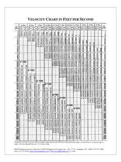
10 A range of Mannings n valuesof for clean water was alsodetermined for this same high-performance cement lining in this same42 Utah State testing program. TheUtah State data also showed theresulting Darcy friction factors f for thehigh-performance cement lining, whenplotted vs. Reynolds number, very closelyapproximate the smooth pipe curve asshown on the Moody of Water InDuctile Iron Pipe17-5 Flow of Water in Ductile Iron PipeHazen- williams c =140*Loss of Head shown is per 1,000 feet of pipeline. Table is based on 4"-64" AWWA C104 single-thicknesscement-lined ductile iron pipe.