Transcription of Hydraulic Design of Sewers and Storm Water Drains Lecture ...
1 Module 7: Hydraulic Design of Sewers and Storm Water Drains Lecture 7: Hydraulic Design of Sewers and Storm Water Drains Hydraulic Design OF Sewers AND Storm Water Drains General Consideration Generally, Sewers are laid at steeper gradients falling towards the outfall point with circular pipe cross section. Storm Water Drains are separately constructed as surface Drains at suitable gradient, either rectangular or trapezoidal section.
2 Sewers are designed to carry the maximum quantity of sanitary sewage likely to be produced from the area contributing to the particular sewer . Storm Water Drains are designed to carry the maximum Storm runoff that is likely to be produced by the contributing catchment area from a rain of Design frequency and of duration equal to the time of concentration. Requirements of Design and Planning of Sewerage system The sewerage scheme is designed to remove entire sewage effectively and efficiently from the houses to the point of disposal.
3 Following aspects should be considered while designing the system. The Sewers provided should be adequate in size to avoid overflow and possible health hazards. For evaluating proper diameter of the sewer , correct estimation of sewage discharge is necessary. The flow velocity inside the sewer should neither be so large as to require heavy excavation and high lift pumping, nor should be so small causing deposition of the solid in the Sewers . The Sewers should be laid at least 2 to 3 m deep to carry sewage from basement.
4 The sewage should flow under gravity with to full at designed discharge, at the maximum estimated discharge. The sewage is conveyed to the point usually located at low-lying area, where the treatment plant is located. Treatment plant should be designed taking into consideration the quality of raw sewage expected and to meet the discharge standards. Difference Between Water Supply Pipes and Sewers Pipes The major difference between the Water distribution network and sewerage collection system is presented in the Table Table : Comparison between the Water distribution network and sewerage collection system Water Supply Pipes sewer Pipes It carries pure Water .
5 Velocity higher than self-cleansing is not essential, because of solids are not present in suspension. It carries Water under pressure. Hence, the pipe can be laid up and down the hills and the valleys within certain limits. These pipes are flowing full under pressure. It carries contaminated Water containing organic or inorganic solids which may settle in the pipe. It can cause corrosion of the pipe material. To avoid deposition of solids in the pipes self-cleansing velocity is necessary at all possible discharge.
6 It carries sewage under gravity. Therefore it is required to be laid at a continuous falling gradient in the downward direction towards outfall point. Sewers are Design to run partial full at maximum discharge. This extra space ensures non-pressure gravity flow. This will minimize the leakage from sewer , from the faulty joints or crack, if any. Provision of Freeboard in Sewers Sanitary Sewers Sewers with diameter less than m are designed to run half full at maximum discharge, and Sewers with diameter greater than m are designed 2/3 to full at maximum discharge.
7 The extra space provided in the Sewers provides factor of safety to counteract against the following factors: 1. Safeguard against lower estimation of the quantity of wastewater to be collected at the end of Design period due to private Water supply by industries and public. Thus, to ensure that Sewers will never flow full eliminating pressure flow inside the sewer . 2. Large scale infiltration of Storm Water through wrong or illegal connection, through underground cracks or open joints in the Sewers .
8 3. Unforeseen increase in population or Water consumption and the consequent increase in sewage production. Storm Water Drains Storm Water Drains are provided with nominal freeboard, above their designed full supply line because the overflow from Storm Water Drains is not much harmful. Minimum of m free board is generally provided in Storm Water Drains . Hydraulic Formulae for Determining Flow Velocities Sewers of any shape are hydraulically designed as open channels, except in the case of inverted siphons and discharge lines of pumping stations.
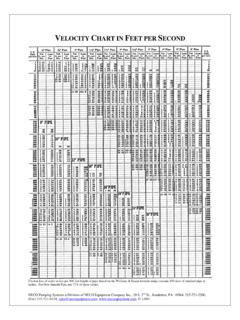
9 Following formulae can be used for Design of Sewers . 1. Manning s Formula This is most commonly used for Design of Sewers . The velocity of flow through Sewers can be determined using Manning s formula as below: Where, v = velocity of flow in the sewer , m/sec r = Hydraulic mean depth of flow, m = a/p a = Cross section area of flow, m2 p = Wetted perimeter, m n = Rugosity coefficient, depends upon the type of the channel surface , material and lies between to For brick sewer it could be and for stone facing Sewers .
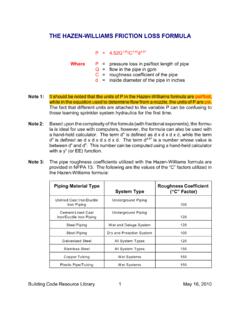
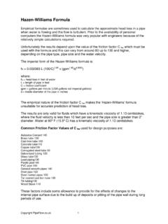
10 1/22/3srn1v= s = Hydraulic gradient, equal to invert slope for uniform flows. 2. Chezy s Formula Where, C is Chezy s constant and remaining variable same as above equation. 3. Crimp and Burge s Formula 4. Hazen- Williams Formula V = C The Hazen-Williams coefficient C varies with life of the pipe and it has high value when the pipe is new and lower value for older pipes. For example for RCC new pipe it is 150 and the value recommended for Design is 120, as the pipe interior may become rough with time.