Transcription of THE HAZEN-WILLIAMS FRICTION LOSS FORMULA
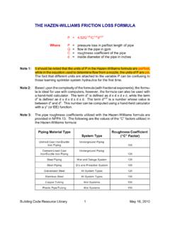
1 Building Code Resource Library1 May 16, 2010 THE HAZEN-WILLIAMS FRICTION loss FORMULAP= P=pressure loss in psi/foot length of pipeQ=flow in the pipe in gpmC=roughness coefficient of the piped=inside diameter of the pipe in inchesNote 1:It should be noted that the units of P in the HAZEN-WILLIAMS FORMULA are psi/foot,while in the equation used to determine flow from a nozzle, the units of P are fact that different units are attached to the variable P can be confusing tothose learning sprinkler system hydraulics for the first 2:Based upon the complexity of the FORMULA (with fractional exponents), the formu-la is ideal for use with computers, however, the FORMULA can also be used witha hand-held calculator.
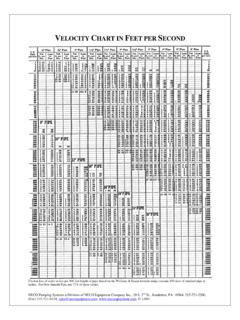
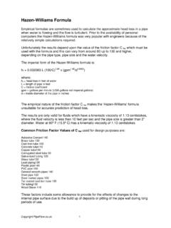
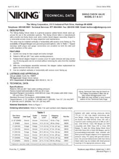
2 The term d is defined as d x d x d x d, while the term4d is defined as d x d x d x d x d. The term d is a number whose value d and d. This number can be computed using a hand-held calculator45with a y (or EE) 3:The pipe roughness coefficients utilized with the HAZEN-WILLIAMS FORMULA areprovided in NFPA 13. The following are the values of the C factors utilized inthe HAZEN-WILLIAMS FORMULA :Piping Material TypeSystem TypeRoughness Coefficient ( C Factor)Unlined Cast Iron/DuctileIron PipingUnderground Piping100 Cement-Lined CastIron/Ductile Iron PipingUnderground Piping120 Steel PipingWet and Deluge System120 Steel PipingDry and Preaction System100 Galvanized SteelAll System Types120 Stainless SteelAll System Types150 Copper TubingWet Systems150 Plastic Pipe/TubingWet Systems150 Building Code Resource Library2 May 16, 2010 Note 4:NFPA 13 requires that steel pipe used in a sprinkler or a standpipe system beeither Schedule 10 or Schedule 40 pipe.
3 The term schedule refers to theminimum wall thickness of the steel pipe. Steel pipe with other pipe wall thick-nesses are permitted to be used when the pipe is specially 5:NFPA 13 indicates that steel pipe with a wall thickness of less than Schedule 40is not permitted to be threaded or be provided with cut groove (unless the pipeis specially listed). This requirement means that Schedule 10 pipe much beconnected using either grooved couplings with roll grooves or with plain end 6:A cut groove is a grove which is formed by removing a portion of the wall ofsteel pipe. A roll grove is a grove which is formed by pressing an indentationonto the pipe. Grooved couplings are used to connect grooved 7:NFPA 13 requires that copper tubing used in a sprinkler or standpipe system beeither Type K, L or 8:The following are the inside diameters of Schedule 10 and Schedule 40 steelpipe:STEEL PIPEI nside DiameterNominalPipe Size(inches)Outside Diameter(inches)Schedule 10(inches)Schedule 40(inches) Code Resource Library3 May 16, 2010 Note 9:3-1/2 inch and 5 inch pipe are no longer manufactured.
4 Information on thesetwo pipe sizes is provided because these pipe sizes may be utilized in olderexisting 10:The following are the inside diameters of Type K, L and M copper tubing:COPPER TUBINGI nside DiameterNominalTube Size(Inches)OutsideDiameter(Inches)Type K(Inches)Type L(Inches)Type M(Inches)3 * * * * *Copyright 2010 Richard C. SchulteAll Rights Reserv