Transcription of An Introduction to Design of Dewatering Systems
1 An Approved Continuing Education Provider PDHonline Course C802 (2 PDH) An Introduction to Design of Dewatering Systems J. Paul Guyer, , 2015 PDH Online | PDH Center 5272 Meadow Estates Drive Fairfax, VA 22030-6658 Phone & Fax: 703-988-0088 PDHonline Course C802 2015 J. Paul Guyer Page 2 of 64 An Introduction to Design of Dewatering Systems J. Paul Guyer, , CONTENTS 1. ANALYSIS OF GROUNDWATER FLOW 2. MATHEMATICAL AND MODEL ANALYSES 3. FLOW NET ANALYSES 4. ELECTRICAL ANALOGY SEEPAGE MODELS 5. NUMERICAL ANALYSES 6. WELLPOINTS, WELLS, AND FILTERS 7. PUMPS, HEADERS, AND DISCHARGE PIPES 8. FACTORS OF SAFETY 9. Dewatering OPEN EXCAVATIONS 10.
2 Dewatering SHAFTS AND TUNNELS 11. PERMANENT PRESSURE RELIEF Systems 12. FREEZING 13. CONTROL OF SURFACE WATER (This publication is adapted from the Unified Facilities Criteria of the United States government which are in the public domain, have been authorized for unlimited distribution, and are not copyrighted.) (Figures, tables and formulas in this publication may at times be a little difficult to read, but they are the best available. DO NOT PURCHASE THIS PUBLICATION IF THIS LIMITATION IS NOT ACCEPTABLE TO YOU.) PDHonline Course C802 2015 J. Paul Guyer Page 3 of 64 1. ANALYSIS OF GROUNDWATER FLOW. Design OF A Dewatering and pressure relief or groundwater control system first requires determination of the type of groundwater flow (artesian, gravity, or combined) to be expected and of the type of system that will be required.
3 Also, a complete picture of the groundwater and the subsurface condition is necessary. Then the number, size, spacing, and penetration of wellpoints or wells and the rate at which the water must be removed to achieve the required groundwater lowering or pressure relief must be determined. IN THE ANALYSIS OF ANY Dewatering SYSTEM, the source of seepage must be determined and the boundaries and seepage flow characteristics of geologic and soil formations at and adjacent to the site must be generalized into a form that can be analyzed. In some cases, the Dewatering system and soil and groundwater flow conditions can be generalized into rather simple configurations. For example, the source of seepage can be reduced to a line or circle; the aquifer to a homogeneous, isotropic formation of uniform thickness; and the Dewatering system to one or two parallel lines or circle of wells or wellpoints.
4 Analysis of these conditions can generally be made by means of mathematical formulas for flow of groundwater. Complicated configurations of wells, sources of seepage, and soil formations can, in most cases, be solved or at least approximated by means of flow nets, electrical analogy models, mathematical formulas, numerical techniques, or a combination of these methods. ANY ANALYSIS, EITHER mathematical, flow net, or electrical analogy, is not better than the validity of the formation boundaries and characteristics used in the analysis. The solution obtained, regardless of the rigor or precision of the analysis, will be representative of actual behavior only if the problem situation and boundary conditions are adequately represented. An approximate solution to the right problem is far more desirable than a precise solution to the wrong problem. The importance of formulating correct groundwater flow and boundary conditions, cannot be emphasized too strongly.
5 PDHonline Course C802 2015 J. Paul Guyer Page 4 of 64 METHODS FOR Dewatering AND PRESSURE RELIEF and their suitability for various types of excavations and soil conditions are described in the technical literature. The investigation of factors relating to groundwater flow and to Design of Dewatering Systems are discussed in the technical literature. Mathematical, graphical, and electroanalogous methods of analyzing seepage flow through generalized soil conditions and boundaries to various types of Dewatering or pressure relief Systems are presented in the technical literature. OTHER FACTORS THAT have a bearing on the actual Design of Dewatering , permanent drainage, and surface- water control Systems are considered in this discussion.
6 THE FORMULAS AND FLOW NET PROCEDURES presented in this discussion are for a steady state of groundwater flow. During initial stages of Dewatering an excavation, water is removed from storage and the rate of flow is larger than required to maintain the specified drawdown. Therefore, initial pumping rates will probably be about 30 percent larger than computed values. PDHonline Course C802 2015 J. Paul Guyer Page 5 of 64 2. MATHEMATICAL AND MODEL ANALYSES. GENERAL. Design . Design of a Dewatering system requires the determination of the number, size, spacing, and penetration of wells or wellpoints and the rate at which water must be removed from the pervious strata to achieve the required groundwater lowering or pressure relief.
7 The size and capacity of pumps and collectors also depend on the required discharge and drawdown. The fundamental relations between well and wellpoint discharge and corresponding drawdown are presented in this discussion. The equations presented assume that the flow is laminar, the pervious stratum is homogeneous and isotropic, the water draining into the system is pumped out at a constant rate, and flow conditions have stabilized. Procedures for transferring an anisotropic aquifer, with respect to permeability, to an isotropic section are presented in the technical literature. SLOTS AND WELLS. The equations referenced are in two groups: flow and drawdown to slots and flow and drawdown to wells. Equations for slots are applicable to flow to trenches, French drains, and similar drainage Systems . They may also be used where the drainage system consists of closely spaced wells or wellpoints.
8 Assuming a well system equivalent to a slot usually simplifies the analysis; however, corrections must be made to consider that the drainage system consists of wells or wellpoints rather than the more efficient slot. These corrections are given with the well formulas discussed below. W hen the well system cannot be simulated with a slot, well equations must be used. The equations for slots and wells do not consider the effects of hydraulic head losses Hw in wells or wellpoints; procedures for accounting for these effects are presented separately. RADIUS OF INFLUENCE R. Equations for flow to drainage Systems from a circular seepage source are based on the assumption that the system is centered on an island of radius R. Generally, R is the radius of influence that is defined as the PDHonline Course C802 2015 J.
9 Paul Guyer Page 6 of 64 radius of a circle beyond which pumping of a Dewatering system has no significant effect on the original groundwater level or piezometric surface. W here there is little or no recharge to an aquifer, the radius of influence will become greater with pumping time and with increased drawdown in the area being dewatered. Generally, R is greater for coarse, very pervious sands than for finer soils. If the value of R is large relative to the size of the excavation, a reasonably good approximation of R will serve adequately for Design because flow and drawdown for such a condition are not especially sensitive to the actual value of R. As it is usually impossible to determine R accurately, the value should be selected conservatively from pumping test data or the technical literature.
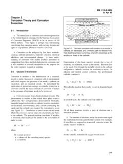
10 WETTED SCREEN. There should always be sufficient well and screen length below the required drawdown in a well in the formation being dewatered so that the Design or required pumping rate does not produce a gradient at the interface of the formation and the well filter (or screen) or at the screen and filter that starts to cause the flow to become turbulent. Therefore, the Design of a Dewatering system should always be checked to see that the well or wellpoints have adequate wetted screen length hws or submergence to pass the maximum computed flow. The limiting flow qc into a filter or well screen is approximately equal to PDHonline Course C802 2015 J. Paul Guyer Page 7 of 64 Figure 1 Head at center of fully and partially penetrating circular slots; circular source; artesian flow.