Transcription of An Optimum Height for an Elevated HF Antenna
1 32 QEX May/June 2011 Kazimierz Kai Siwiak, KE4PT10988 NW 14th St, Coral Springs, FL 33071; Optimum Height for an Elevated HF Antenna 1 Notes appear on page is the best Height for your Antenna ? The author considers factors that can help you are two ways to think about Antenna and propagation prob-lems in linear media: in transmit mode and in receive mode. By the reciprocity theorem both methods will predict the same performance. We will view the problem of finding an Optimum Height for HF anten-nas in receive mode rather than in transmit mode, because this reveals very interesting insights.
2 For example, the field-strength at the receiv-ing location is the result of an interference pattern between waves that arrive by a direct path added to the wave reflected from the earth s surface. The addition of these two waves results in a standing wave versus Height for the field strength at the receiving location. Because this vertical standing wave has peaks and can have deep nulls, there is an Optimum placement for an Antenna . In the equivalent transmit mode point of view, far-field transmit patterns are calculated as an interference pattern between the direct wave and a ground reflected wave, but as The ARRL Antenna Book explains, that point of view obscures the physical meaning of take-off angle, so we can t directly appreciate what happens when an Antenna is By viewing the problem in receive mode, however, we see, among other things, that waves arriving from the lowest arrival angle do not always result in the best link margin to a DX station.
3 We can also see that low antennas can work surprisingly well for DX, and that the best Height for vertically polarized antennas is not the same as for horizontally polarized this analysis it is easy show that the Optimum Antenna Height depends on frequency, polarization, properties of the earth at the reflection point, and on the arrival angle from the wave source in the ionosphere. While surface roughness is considered, there is also a terrain dependence, which for simplicity will not be considered here; see Dean Straw s terrain analysis program HFTA in the 21st edition of The ARRL Antenna Book. Furthermore, since the apparent wave earth reflection point is usually distant from the Antenna , it is not important what the earth looks like directly under an Elevated Antenna .
4 What is important is the earth s properties at the reflection point typi-cally hundreds to thousands of meters distant from the tower. This is an idealized problem where we allow for surface roughness, but we assume an earth that is smooth enough so that we can apply spherical earth begin by laying a foundation based on a spherical earth geom-etry for the propagation of waves to the receiving location. The reflec-tion properties of ground and sea water are shown to affect how the reflected wave combines in constructive and destructive interference with the direct wave. Optimum heights are found for desired ranges of arrival angles and for multiple bands.
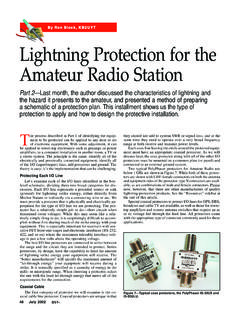
5 Finally, path link margins are estimated for multi-hop propagation. We discover that a range of take-off angles must be accommodated for Optimum Earth GeometryBecause we are dealing with distances that approach the earth s horizon, we calculate the direct and earth-reflected paths using spher-ical-earth reflection geometry. The solution to the spherical earth geometry given in Chapter 2 of M. I. Skolnik s Radar Handbook involves a cubic equation to find the arc distance Gb to the reflection ()32223220bbeantibeantGGGGahhGahG + ++= [Eq 1] where: hant is the Height at the receiving Antenna , ae is the earth s radius,Ionospheric pointhantRiRbDtrAntennaTGbEarth surfaceReflectionGiG=Gb+Gihi Center of EarthpointEarth radius aeFigure earth geometry, shown with an exaggerated Height dimension.
6 Source: based on [2]. Figure 1 Spherical earth geometry, shown with an exaggerated Height dimension. Source: based on information from Radar Handbook (see Note 2). QEX May/June 2011 33 and the distances G and Gb are functions of the angle T between the local horizon and the direction to the wave source point at Height hi in the ionosphere. Figure 1 shows the spherical earth reflection geom-etry and identifies all of the angle T is also called the take off angle and the local eleva-tion angle. See the ARRL website files update to The ARRL Antenna The direct wave arrives along path Dir, and the reflected path includes distance Ri from the ionosphere to the earth reflection point and Rb from the reflection point to the receiving location.
7 The reflec-tion occurs at the arc distance Gb from the base of the Antenna tower, and as the direct wave arrival angle T deceases, then the arc distance to the reflection point increases. Our chief concern is with the differ-ence in the path lengths, R = (Rb + Ri Dir ) [Eq 2]and with the surface reflection coefficient at the reflection point because these determine the nature of the field variation versus Height , Coefficients and Combined WavesThe plane wave reflection coefficients H for horizontal and V for vertical polarization are used to find the reflection from land or sea on a spherical earth.
8 (See Chapter 6 of Radiowave Propagation and Antennas for Personal ) The reflection coefficient is modified by the divergence factor D and surface roughness Sr factor. The wave divergence factor is: sin12bie2 GGD1aG = + [Eq 3]where is the angle of incidence on the earth s surface. The sur-face roughness factor is:()0expIsin2rsdS(r)(r);r2kh()= = [Eq 4]where: I0 is the modified Bessel functionk = 2 f / c is the wave numberf is the signal frequency in Hzc is the speed of light in m/s. The roughness factor for the reflected wave is based on a rough-ness factor originally derived for a ratio of rough-sea to smooth-sea reflection, and is applied here generally to an earth reflection.
9 The sur-face roughness parameter hsd is the standard deviation of the surface Height distribution in the reflection region. The complete reflection coefficients are thus H Sr D and V Sr D for a rough spherical earth. The reflected term fields are also multiplied by d = Dtr / (Rb + Ri) to account for the difference in free space loss due to the differential dis-tance between the direct and reflected waves. For this study we will assume that horizontally polarized power is added to vertically polarized power in a ratio, PHV. For substantially horizontally polarized waves, PHV is chosen here to be between 10 and 20, and for substantially vertically polarized waves, PHV is between and The polarization impurity primarily results in a slight reduction of the depths of nulls in the vertical standing wave patterns.
10 The two polarization components are added as power because the polarization is decomposed by the ionosphere into elliptical polariza-tion, (see Ionospheric Radio Propagation5) and reflections from a rough surface are generally random and time-variable. The expres-sion for the signal power, P normalized to the free space value, of the combined waves at the receiving Height , hant is:[][]expexp22 HVHrVrHVP1(jkR)SDd1(jkR)SDdP1P+ + + =+ [Eq 5]The unity terms in each of the brackets represent the direct wave amplitude, and the remaining terms are the reflected wave, each in ratio to the free space value.