Transcription of Analog / Digital Gauge System INSTALLATION AND …
1 MAN 650314:J 1 VHX Analog / Digital Gauge System INSTALLATION AND OPERATION MANUAL Please read this before beginning INSTALLATION or wiring. IMPORTANT NOTE! This System has an odometer preset option that is only available for the first 100 miles of operation. See odometer preset section (pg 27) for instructions and setup information. MAN 650314:J 2 Thank you for purchasing a VHX System from DAKOTA Digital . VHX is a loose acronym for Vehicle Hybrid Instrument Systems. Representing the latest electronic dashboard technology for the street rodder, car, and truck enthusiast alike, the VHX System combines modern Digital electronics with a traditional look to give the driver up-to-date and accurate information on the operation of his or her vehicle.
2 Fully lit needles, backlit faces, and highly visible LCD message centers are a few features that make the VHX lineup stand out from other aftermarket instrumentation. The VHX System boasts excellent daytime visibility and while under computer control, fully backlit and dimmable for nighttime driving. Monitoring solid state sensors with microprocessor technology and driving precision stepper motors, the VHX dashboard gives the driver unparalleled accuracy. User-customizable display feedback and additional features not typically found on any other brand or type of instrumentation are standard in the VHX System .
3 Digital accuracy and solid state reliability will give you, the driver, quality service for miles down the road that includes a limited lifetime warranty on a product engineered and manufactured in the USA! VHX INSTRUMENT System FEATURES Digital LCD displays Each of the six Analog gauges can be displayed here as well as additional functions listed below. Features are available on either display (L or R). Mileage readings Million mile odometer Two (A/B) re-settable trip mileage ( ) Re-settable service mileage (0-9999 countdown) Performance readings High speed recall.
4 This can be manually reset during normal operation. High rpm recall. This can be manually reset during normal operation. 0-60 mph (0-100kmh) time. mile time. This can manually reset during normal operation. mile end speed (trap speed). This is reset when the mile time restarts. Hour meter Resettable hours ( ) English/metric conversion Alternate speed and temperature can be displayed in LCD display. Built-in Indicators Left/Right Turn signal indicators High Beam indicator Check Engine indicator Brake warning indicator 4x4 indicator Wait to Start indicator Cruise control indicator Gear position indicator which displays full gear word with use of Dakota Digital GSS-2000 (purchased separately) Special outputs Shift output to activate external light Selectable 2000ppm or 4000ppm speed output for cruise or ECM Demonstration mode Holding Switch 2 while turning on the key will start the System going through a preset sequence of readings.
5 To exit the demo mode, turn the key off. You may also wire up a separate switch to power the gauges for demo mode without powering the entire vehicle. Auxiliary Gauge readings in LCD message displays with expansion bus interface modules (BIM) MAN 650314:J 3 TYPICAL VHX DISPLAY LAYOUTS Tach/LCD2 Message Center Speed/LCD1 Message Center Tach/LCD2 Message Center Tach/LCD2 Message Center Tach/LCD2 Message Center Speed/LCD1 Message Center Speed/LCD1 Message Center Speed/LCD1 Message Center MAN 650314:J 4 WARNING These are precision instruments and must be handled with care.
6 Do not disassemble gauges. CARE AND CLEANING Never open the System or attempt to remove the needles as the calibration of the instrument System could be thrown off. All systems are calibrated and tested before they leave Dakota Digital . The clear lens on the front of the VHX System can be cleaned with a mild soap and water solution or common glass cleaners. Use a soft cloth such as a micro-fiber for wiping the lens clean. MOUNTING SYSTEMS Most VHX systems and kits will come with a separate instruction sheet with mounting details. Follow this sheet for mounting the actual display System in the dash, and then refer to this manual for wiring and operation instructions.
7 CONTROL BOX MOUNTING Once the display panel is in place, mount the control box within reach of the supplied networking cable (approximately three (3) feet). If a longer cable is required, replacement CAT5 cables are available online as well as your local electronics stores. Choose a mounting location that will allow you access to wire all of the inputs on either side of the control box. Double sided tape, hook and loop fasteners or screws in the two tabs on the case work fine for securing the control box under the dash. When selecting a mounting location, avoid placing the control module next to or just opposite of the firewall from ignition components, ie: Ignition coil, HEI, etc.
8 Ignition components can emit tremendous amounts of electrical noise, affecting the operation of electrical components which can cause erratic operation. **If you are purchasing a longer network cable to connect the display System to the control box please make sure to get a CAT 5, CAT5E, or CAT6 patch cable and NOT a cross over cable. Replacement cable should be seven feet or less. MAN 650314:J 5 WIRING While the control box contains several connections, the wiring is straightforward. Depending on how many auxiliary functions you want displayed, not every terminal will be used in most applications.
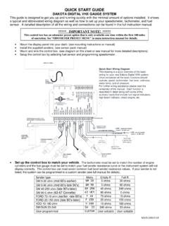
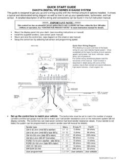
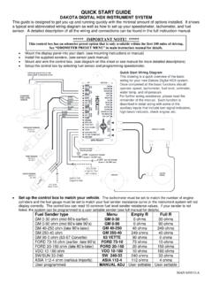
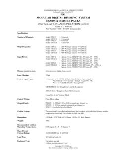
9 On the pages that follow, we describe the function of each terminal, what they do, and how to wire them. MOMENTARY SW2 MOMENTARY SW1 CAT 5 CABLE(TO DISPLAY)DISPLAY PANELSTATUS LEDDIM-1 OptionalCruise ControlEngage OutputGlow Plug RelayorWait to start outputECU/ECMcheck engineoutputBIM CONNECTIONONLY!4x4transfer caseswitchDAKOTA DIGITALGSS UNIT1-Wire outputRIGHT TURNSIGNAL WIREO ptionalLEFT TURNSIGNAL WIREHIGH BEAMWIREPARKING BRAKESWITCHSPEED OUT(2k or 4k PPM)Connect to tail light circuit,LED backlights will turn onwhen termianl has +12 VLight or Buzzer(4 Watts or more)Tail LightLight or Buzzer(4 Watts or less)
10 RelayEXSISTINGFUEL LEVELSENSORREDWHITEBLACKBLUEBROWNA dditional ground wire to fuelsensor body or mounting SENSOR SEN-03-8 0-100 PSITEMP SENSOR SEN-04-5 100-300 FPULSE GENERATORECU/ECMS peed OutputREDWHITEBLACK+12V KEY ON POWER (fused 5 - 20 AMP max)Connect to main chassis groundIgnition Coil(negative side) - +ECU/ECMor Ignition Box(tach output)SPEED SENSORSEN-01-516k PPM ACC. POWER CONST. POWER GROUND TACH WARN SPD + SPD SND SPD - SPD OUT SW2 (-) SW1 (-) ADJ SND ADJ - WTR SND WTR - OIL + OIL SND OIL - RESERVED (SEE MANUAL) FUEL SND FUEL - WAIT (+) CRUISE (-) GEAR (1 WIRE) 4x4 (-) RIGHT (+) LEFT (+) HIGH (+) BRAKE (-) CHECK ENG (-)VHXCONTROL DIM (+)+12V CONSTANT POWER (fused 5 - 20 AMP max)BARE MAN 650314.