Transcription of Analysis of Airfoil Flow Pattern using CFD - IJERT
1 Special Issue - 2018 International Journal of Engineering Research & Technology ( IJERT ). ISSN: 2278-0181. Confcall - 2018 Conference Proceedings Analysis of Airfoil Flow Pattern using CFD. V. Gayathri Kanimozhi, Department of Aeronautical Engineering, Parisutham Institute of Technology and Science, Thanjavur, Tamil Nadu, India. Abstract In this paper, Flow Pattern of Airfoil over two- basic dissimilarities between symmetric and asymmetric dimensional subsonic flow at a various angle of attacks aerofoil like at zero degree angle of attack, asymmetric operating at Reynolds's number is obtained. Analysis on the airfoils can generate lift, while a frequent inverted flights Airfoil profile is carried out to find the values of CD and CL suits symmetric Airfoil as in the case of an aerobatic at different values of angle of result shown by airplane.
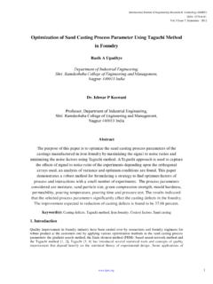
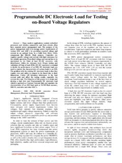
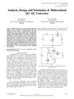
2 Thus without boundary layer separation, we can CFD has closely agreed with experiment result, thus CFD is a mature tool to predict the performance of test section at use various angles. Subsonic airfoils have a round leading any angle of attack. edge around which it is naturally insensitive to angle of attack [2]. Keywords Flow separation, angle of attack, CFD, coefficient of lift and coefficient of drag, pressure coefficient etc. I. INTRODUCTION. It is fact of common experience that a body in motion through a fluid experiences a resultant force mainly a resistance to a motion. A class of body exists, for which the component of resultant force normal to the direction of motion is many times greater than the component resisting the motion Fig 1. Airfoil Geometry [1].
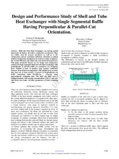
3 An Airfoil is a streamlined body found in airplanes, propellers, turbines and many other applications. When an The point at front of the Airfoil that has maximum Airfoil body passing through any fluid it produces an curvature is known as a Leading edge. The trailing edge is aerodynamic force which is due to pressure distribution defined as the point of minimum curvature at the rear of over the body surface and shear stress distribution over the Airfoil . The straight line joining the leading edge and the body surface. This aerodynamic force can be resolved trailing edge of Airfoil section is chord line. Chamber line into two components known as lift and drag. The force is the locus of point's midway between the upper and which acts in perpendicular to the direction of motion is lower surface of an Airfoil .
4 The Angle of attack is called as lift force, and the force which is parallel to the measured by taking a difference between free stream direction of motion is called as drag force. Lift is velocity and chord line. It is the ratio of a span of an generated by aerofoil primarily depends upon surface area aerofoil to the chord length of an aerofoil is called as the and angle of attack. The drag force mainly depends upon Aspect ratio. the body surface and fluid which is flows over it. This lift and drag force are obtained with the help of wind tunnel. III. COMPUTATIONAL FLUID DYNAMICS (CFD). A wind tunnel is a machine which used in aerodynamic research to study the effects of air moving on solid Computational Fluid Dynamics is a branch of fluid objects. A wind tunnel consists of a tubular passage with mechanics that analyze problems involving fluid flow by the object under test mounted in the middle.
5 Air is then using numerical Analysis and data structure. The moving past the object by a powerful fan system or other interaction of liquid and gases with a surface defined by means. The test object often called a wind tunnel model, boundary condition are solved with the help of computers, is instrumented with suitable sensors to measure which performs its calculations. CFD is commonly aerodynamic forces, pressure distribution, or other accepted as referring to the board topic encompassing the aerodynamics-related characteristics. The advance in numerical solution, by computational methods, of the computational fluid dynamics modeling on a high speed governing equations which describe fluid flow, the set of digital computer has reduced the demand for wind tunnel Navier-stokes equation, continuity and any additional testing.
6 However, CFD results are still not completely conservation equation like energy or species reliable and wind tunnels are used to verify CFD concentration. CFD is considered as a bridge between the predictions. pure experiment and pure theory. Computational fluid II. GEOMETRY dynamics predict the performance of a system before In aerodynamics, Airfoil design is a major facet. Different flight regimes show different results. There are Volume 6, Issue 14 Published by, 1. Special Issue - 2018 International Journal of Engineering Research & Technology ( IJERT ). ISSN: 2278-0181. Confcall - 2018 Conference Proceedings installing it in real life. CFD predict which design changes A typical graph of coefficient of lift against the angle of are most crucial to enhance the performance.
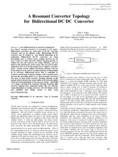
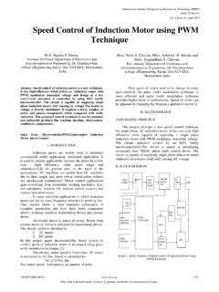
7 Moreover, attack of the Airfoil section is studied. One of the first there are several unique advantages of CFD over things noticed is the fact that at an angle of attack of 0 , experimental-based fluid system design. there is a positive coefficient of lift, and, hence, positive lift. One must move to a negative angle of attack to obtain CFD provides more detail and comprehensive zero lift coefficients. It will be remembered that this angle information. is called the angle of zero lift. A symmetric Airfoil was shown to have an angle of zero lift equal to 0 as might be Ability to study system under zero hazardous conditions expected. From the diagram we can see that as an angle of at and beyond their normal performance limits. attack increased coefficient of lift associated with it is also increases up to a certain maximum point known as a Power consumption of CFD is low as compared to a stall angle.
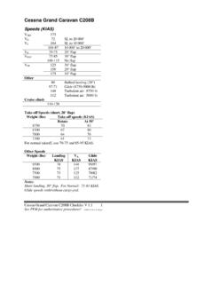
8 Above this angle, however, the lift coefficient wind tunnel. reaches a peak and then declines. The angle at which the lift coefficient (or lift) reaches a maximum is called the CFD Analysis of temperature, velocity, and chemical stall angle. Beyond the stall angle, one may state that the concentration distribution can help an engineer to Airfoil is stalled and a remarkable change in the flow understand the problem correctly and provide ideas for Pattern has occurred. getting the best resolution. Originally the value of drag coefficient is zero at zero IV. ANGLE OF ATTACK degree angle of attack. But then as we increase an angle of attack drag coefficient will also increase before and When you stretch your arm out through window of car after stall condition occurs.
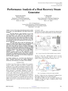
9 Minimum drag coefficient which moves at high speed, you can feel that your arm occurs at a small positive angle of attack corresponding to pull back while colliding with oncoming air and when a positive lift coefficient and builds only gradually at the you hold your hand outside of window in parallel to the lower angles. Near to the stall angle, C_D increase rapidly direction of road and just inclined it in certain angle, you because the greater amount of turbulent and separated feel like your hand push upward it is because of oncoming flow occurred. air strikes at your hand. Angle Of Attack is the angle between the reference line of a body and relative wind or V. FLOW SAPERATION. oncoming air [3]. On an Airfoil such as one on a wind All solid objects travelling through fluid experience turbine, it is the angle between the chord line and relative viscous forces occur in the layer of fluid close to the solid wind vector.
10 The relation between an angle of attack, the surface which acquires a boundary layer of fluid around coefficient of lift and coefficient of drag is as follows: them. Boundary layers can be in the form of laminar or turbulent. By calculating the Reynolds number of the local flow conditions we can make a decision that the flow is laminar or turbulent. When the boundary layer travels far enough against an adverse pressure gradient and at the same time the speed of the boundary layer relative to the object falls almost to zero then Flow separation occurs. In aerodynamics, flow separation can often result in increased drag. For this reason, much effort and research have gone into the design of aerodynamic and hydrodynamic surfaces which delay flow separation and keep the local flow attached for as long as possible.