Transcription of API RP 2A - Recommended Practice for Planning, Designing ...
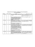
1 StandardEditionSectionInquiry #QuestionReply2A-WSD21st Edition, Dec. 2000 General2A-02-09 Background: API has two standards for fixed offshore platforms: API 2A-LRFD and API 2A WSD and we are not sure which standard use. RP 2A WSD states in the Foreword that the AISC Load & Resistance Factor Design (LRFD), First Edition is not Recommended for 1: Can we use the latest edition of AISC-LRFD (AISC-360-05) for the design of offshore structures?Question 2: We have to perform an assessment on a platform structure designed 20 years ago according to API 2A-WSD. Can we use API 2A-LRFD (of course using the loading, factors, etc from the same standard), or it is required to use API 2A WSD?Reply 1: No. Please refer to ISO 19902, Petroleum and natural gas industries Fixed steel offshore structures. ISO 19902 was based on API 2A-LRFD and has been updated to reflect the latest 2: It is not Recommended to mix the principles of WSD with LRFD.
2 If the structure was designed using WSD, it should be assessed using WSD. Similarly, if the structure was designed to LRFD, it should be assessed using LRFD. API is developing RP 2 SIM, Structural Integrity Management, to address the assessment of existing structures, which is planned for publication in Edition, Dec. 2000 General2A-02-11It seems that there is no specific recommendation in API 2A-WSD for a factor of safety (FOS) for jacket overturning prior to pile installation. What is the Recommended minimum FOS for overturning?See API 2A-WSD, Section Edition, Dec. : In Section , Item 11, it is stated that the wave crest should be positioned relative to the structure .. It should be kept in mind that (a) maximum base shear ..; (b) in special cases of waves with low steepness and an opposing current, maximum global structure force may occur near the wave trough rather than near the wave crest.
3 Question: Would you please clarify whether Case (b) is specific to some regions where wave and current directions could be opposite, or in all regions we have to apply both cases where (1) current and wave directions are opposite and (2) current and wave directions are same?The requirement is to position the wave crest relative to the structure so that total base shear and overturning moment have their maximum values. There is no general statement concerning the worldwide geographic locations that are likely to experience waves and currents in opposite directions. For design, site-specific environmental data should be obtained from a metocean consultant. Depending on the nature of the data, analyzing both cases may or may not be necessary. In any case, the sentence in (b) is simply a warning that in the case of low steeepness and opposing current the wave positions that originate the largest loads on the structure may be close to the trough rather than to the Edition, Dec.
4 : Section gives shape coefficient values for perpendicular wind approach angles on each projected area . This section further states that for overall projected area of the platform the Cs value is Most offshore platform facilities are rectangular or square shaped in plan, that is, they have two flat projected faces at 90 degrees to each other. For wind approach perpendicular to these, the interpretation is : Are wind approach angles that are not perpendicular to these faces considered in this section?Non-perpendicular wind forces are addressed as ) Compute the projected area perpendicular to the wind, apply the full wind pressure to that projected area , and distribute the forces to joints exposed to that wind. The forces are resolved into components parallel to global axes for application to ) For a unit wind force, compute the component (direction cosine) of the wind perpendicular to each of the two flat projected faces of the platform.
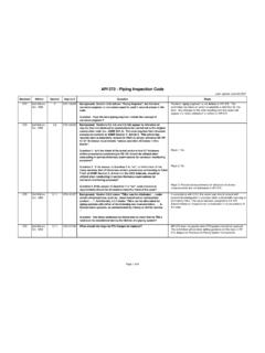
5 Multiply the area of the flat projected face times the component (direction cosine) perpendicular to it and apply the full wind pressure to that reduced area in the component RP 2A - Recommended Practice for planning , Designing , and Constructing Fixed Offshore Platforms Working Stress DesignLast update: January 4, 2014 Page 1 of 8 StandardEditionSectionInquiry #QuestionReplyAPI RP 2A - Recommended Practice for planning , Designing , and Constructing Fixed Offshore Platforms Working Stress DesignLast update: January 4, 2014 2A-WSD21st Edition, Dec. : API RP2A-WSD, Section , states that for areas with low seismic activity between and , all requirements are satisfied if the rare, intense earthquake is used for strength requirements and tubular braces are designed for computed joint loads due to rare intense earthquake. In section , the stresses in the tubular chords are computed based on twice the strength level seismic loads in combination with gravity, hydrostatic and buoyancy loads.
6 Question: in low seismic areas, are the chord stresses computed based on twice the rare intense earthquake or twice the strength level seismic loads? The chord stresses should be computed based on the rare intense earthquake (DLE), not twice the DLE. Twice the strength level (SLE) is an approximate method of obtaining the chord stresses for the rare intense earthquake (DLE), and can be used instead (assuming California conditions). If the platform is not in California, the DLE chord stresses should be used. Studies have shown that for offshore California, DLE loads are about twice the SLE loads, hence the factor of two; this is not true in all seismic Edition, Dec. Section of API RP 2A-WSD, it states For the strength requirement, the basic AISC allowable stresses and those presented in Section may be increased by 70 percent . If the allowable is , is it okay to have the allowable stress equal to ( Fy = Fy)?
7 Yes. See Part 4, Paragraph 4 for further explanation. The 70 percent allowable stress increase allows minor yielding but no significant damage to the member for SLE loading. The intent is to provide a simplified estimate of member performance at SLE loading while still using a linear method such as response spectra analysis. This does not mean that the member design is plastic the intent of SLE design is that all members and joints should still be elastic, although they can be above normal allowable and very close to plastic. If the member is deemed as being plastic at SLE loading then it should be redesigned to be elastic (but with little or no allowable). Note that the platform must also pass the DLE requirement that ensures it does not collapse on a global 2 of 8 StandardEditionSectionInquiry #QuestionReplyAPI RP 2A - Recommended Practice for planning , Designing , and Constructing Fixed Offshore Platforms Working Stress DesignLast update: January 4, 2014 2A-WSD21st Edition, Dec.
8 : Section of API RP 2A-WSD states the following. For areas where the strength level design horizontal ground acceleration is in the range of to , inclusive, all of the earthquake requirements, except those for deck appurtenances, may be considered satisfied if the strength requirements (Section ) are met using the ground motion intensity and characteristic of the rare intense earthquake in lieu of the strength level earthquake .. In this event, the deck appurtenances should be designed for the strength level earthquake in accordance with , but the ductility requirement (Section ) are waived, and tubular joints need be designed for allowable stresses specified in Section using the computed joint loads instead of the tensile load or compressive buckling load of the : as per Section , the deck appurtenances that typically do not meet the rigid body criterion are drilling rigs, flare booms, deck cantilevers.
9 Furthermore on the last paragraph, it says Deck-supported structures, and equipment tie-downs, should be designed with a one-third increase in basic allowable stresses, unless the framing pattern, consequences of failure, metallurgy, and/or site-specific ground motion intensities suggest otherwise . The statement of 70% increase in basic allowable stress in the table in Section of JM1 Structural Design Basis is applicable for JM1 jacket and : Is it correct that only the jacket and deck should be checked with a 70% increase in basic allowable stress, but for flare boom structure, it should be checked with a one-third increase in basic allowable stress?Yes. The increase in allowable stresses applies to strength level earthquake check for deck drilling and well servicing structures, while the increase applies ductility level earthquake for jacket and deck framing.
10 API 4F specifies no DLE check for deck drilling and well servicing Edition, Dec. : Section 3) states earthquake loading should be combined with other simultaneous loadings such as gravity, buoyancy, and hydrostatic pressure. Gravity loading should include the platform dead weight (comprised of the weight of the structure, equipment, appurtenances), actual live loads and 75% of the maximum supply and storage loads. Item 4) in that same section states for the strength requirement, the basic AISC allowable stresses and those presented in Section may be increased by 70%Question: Can you show equations similar to ASCE 7-05 that show the load factor for each load and where you apply the 70% increase? Does the increase apply to all loads or earthquake load only? ASCE 7-05 reduces the earthquake load and uses (similar to increase allowable load).API 2A-WSD is based on working stress design that modifies the stress of the steel material to an allowable level that is then compared to the stresses caused by the unfactored design loads.