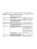
Transcription of API Standard 520 Part II - Sizing, Selection ...
1 StandardEditionSectionInquiry #QuestionReply520 part II5th - Aug. : sizing methods for PSV s are specified in RP 520 part I, Section , where the combination correction factor (Kc) is when a rupture disk is installed. It may result from the consideration of pressure drop in rupture disk. In other words, a 10% pressure drop is considered for rupture disk. RP 520 part II, Section , states when a PRV is installed on a process line, the 3% limit should be applied. Question: How I can meet the 3% limit when I want to use a rupture disk upstream of the PRV? I think these are contradictory 3% inlet loss rule applies to both liquid and vapor applications. The industry has experienced chatter of PRV s in liquid applications.
2 In both liquid and vapor applications, the current recommendation is to use the rated flow capacity of the PRV for sizing the inlet piping. In certain applications where the PRV can be designated as a modulating device, such as with a pilot-operated modulating pressure relief valve, the required relieving capacity can be used to size the inlet piping in lieu of the rated capacity of the 3% rule is currently being investigated as part of a Joint Industry Project which is investigating the applicability of the 3% rule. The API Subcommittee on pressure Relieving Systems is sponsoring this effort and will make modifications to the recommendations in RP 520 part II, as part II5th - Aug. : Twelve production wells are connected to a 6-inch test header approximately 180 metres long via 6-inch flow lines, 16 metres long.
3 The wells are two phase oil and gas with 20 mol % H2S content. A single relief valve set is located as shown near the end of the header with an upstream bursting disc 1: When calculating the suction losses in the inlet piping to the relief valve in accordance with , where is the source of pressure , what is the total length of the PSV inlet line to be considered for suction losses?Question 2: Section states: When a pressure relief valve is installed on a process line, the 3 percent limit should be applied to the sum of the loss in the normally non-flowing pressure relief inlet pipe and the incremental pressure loss in the process line caused by the flow through the pressure relief valve. Do we have to consider the total pressure loss from source through to the PSV inlet, based on the PSV full rated flow, or is the incremental pressure loss the difference between the pressure loss at the PSV rated flow less thepressure loss at the normal process flow?
4 Reply 1: API does not provide consulting on specific engineering problems or on the general application of its standards. Technical inquiries submitted to API must be limited requests for an interpretation of the requirements in a Standard , or to the consideration of revisions based on new data or technology. We recommend you should seek the assistance of a consultant or engineering company familiar with the requirements of the Standard . Reply 2: The intent of is to limit the pressure reduction at the inlet of the pressure relief valve after the valve opens to 3 % of the set pressure , regardless of the cause of overpressure. In addition, the pressure relief valve opening pressure and the maximum allowable accumulated pressure of every component in the protected system must meet applicable code part II5th - Aug.
5 Has specific requirement for inlet isolation valve stem orientation. Section , covering outlet isolation valves, does not specifically address stem orientation. Is the inlet isolation valve stem orientation in applicable to both inlet and outlet isolation valves?Section does not specifically address stem orientation for outlet isolation valves as does Section for inlet isolation valves. However, it is common to orient the stem of any gate valve in the pressure relief path in a horizontal or downward manner to minimize the possibility of internal failure resulting in the pressure relief path being Standard 520 part II - sizing , Selection , & installation of pressure Relieving DevicesPart II, InstallationLast update: October 19, 2007 StandardEditionSectionInquiry #QuestionReplyAPI Standard 520 part II - sizing , Selection , & installation of pressure Relieving DevicesPart II, InstallationLast update: October 19, 2007 521 part II5th - Aug.
6 : Section specifically requires all isolation valves in relief system piping to be full bore. A question arises regarding the use of butterfly valve as isolation valve. I have noted that check valve with locking devices (as in API RP 14E) is : If the butterfly valve is of the high integrity/performance type with tight sealing that comes with a proper locking device, provided if the effective flow area of a butterfly valve meets or exceeds relief requirement, can it be considered as an alternative for relief valve line isolation?No. Butterfly valves do not meet the full bore requirement, because when open, a full bore valve has no internal elements obscuring the line-of-sight through the valve. In addition, there is a potential for internal failure of the butterfly valve causing an obstruction in the PRD inlet line.