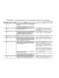
Transcription of API Standard 520 - Sizing, Selection, & Installation …
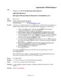
1 StandardSectionInquiry #QuestionReply520 Part I7th - Jan. 2000 1: Is this a correct interpretation of Section in that the backpressure was specified to not exceed the allowable overpressure?Question 2: If my interpretation of is correct, would relief valve manufacturers be required to test their relief valves at 21% overpressure with 21% backpressure in order to offer a certified and ASME coded/stamped relief valve? My concern here is to clarify under what circumstances this section may be invoked if there is a restricted opportunity to take advantage of its benefits due to lack of capability from relief valve manufacturerReply 1: Yes. The latest revision to RP 520 Part 1 is intended to permit the backpressure for a conventional pressure relief valve to go up to but not exceed the allowable overpressure. For cases such as the fire case, and as shown in your examples, a backpressure over 10% is 2: API cannot respond to this question as it is outside the scope of RP 521.
2 You should contact ASME for an Part I7th - Jan. 2000 : Equation in gives a formula for calculating critical flow ratio in terms of "k", which is defined as the ratio of specific heat for any ideal gas. I also see that the ratio of Cp/Cv is being used in calculating F2 in (Equations thru ).Question: Can Equation be used, with k being the ratio of ideal gas specific heats, even if the relieving vapor is non-ideal with a compressibility factor Z = (far from ideal)?Referring to , while ideal gas law behavior (with compressibility factor, Z, included) is generally acceptable for the majority of refinery applications, Appendix B should be referred to for unusual situations in which deviation from ideal behavior is Part I7th - Jan. : Section states that coefficient C, used to calculate the required orifice area for critical gas or vapour relief, should be based on Cp/Cv of the gas or vapour at relieving conditions.
3 This is a change from the previous edition which states that Cp/Cv at Standard conditions should be used. This change can have a significant effect on the required area (up to 15% in calculations we have carried out). Generally using Cp/Cv at relieving conditions will result in a lower required orifice area, however if this does not allow a smaller actual orifice size to be installed ( using Cp/Cv at Standard conditions) it can actually result in a significantly higher rated : Table 7 still gives values of Cp/Cv at Standard conditions, and a value from this table is used in the example in , step e. Is this correct now that C is based on Cp/Cv at relieving conditions?Yes. Section recommends that the ratio of specific heats, k, in the sizing equations should be determined at the inlet relieving conditions. This is a departure from previous editions, which said that k should be based on Standard conditions ( 60 F and atmospheric pressure ).
4 520 Part I7th - Jan. 2000 to , the stated requirements in the example indicate a C4/C5 hydrocarbon mixture with a molecular weight of vapor of 65. It appears that the relieving conditions posed in the example would be such that the hydrocarbon mixture would be a liquid at the inlet instead of a vapor. Are the conditions given in correct?No. Although your observations are correct, the purpose of the example problem was to demonstrate the use of the critical flow equation. The API Subcommittee on pressure -Relieving Systems recognizes the inconsistency with the operating conditions postulated in the example problem. The example will be revised in the Eighth Edition of RP 520 Part I to eliminate this Standard 520 - sizing , selection , & Installation of pressure Relieving DevicesPart I, sizing & SelectionLast update: June 16, 2005 StandardSectionInquiry #QuestionReplyAPI Standard 520 - sizing , selection , & Installation of pressure Relieving DevicesPart I, sizing & SelectionLast update: June 16, 2005 520 Part I7th - Jan.
5 Of the seventh edition (January 2000) of API RP 520, Part I recommends that the ratio of specific heats, k, in the critical flow sizing equations should be determined at the inlet relieving conditions. This is a departure from previous editions which always stated that k should be based on Standard conditions ( 60 F and atmospheric pressure ). It is the committee s opinion that k based on actual inlet conditions will give a better answer and should be used whenever the data is available?The ratio of specific heats, k, for most gases will become unstable near the critical point, and therefore the committee cautions users when the inlet conditions are near the critical point. Table 7 provides k values for some common gases at Standard conditions. If the k at Standard conditions is used, the resulting answer should be example calculations on page 44 and 45 do use the Standard k values from Table 7.
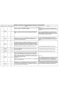
6 The committee will consider making changes to the text as well as the example problems to make it clearer to the reader that the actual values should be used and that the use of Standard values as provided in Table 7 will be conservative in most cases. 520 Part I7th - Jan. 1: Since the effective coefficient of discharge (according API 520) is , the effective discharge area (according API 520) should be ( * ) Is this correct? In this case, is it possible to designate the orifice as a "G" orifice (according table 1 API 526) even if the actual flow capacity is times the actual flow of an orifice area of (orifice "G").Question 2: The same valve has an actual liquid discharge coefficient of Since the actual orifice area is , which is the Standard effective orifice area for liquids ("H"= or "G"= )?Reply 1: Per API RP520 Part 1, The effective orifice size and effective coefficient of discharge specified in API standards are assumed values used for initial selection of a pressure relief valve size from configurations specified in API STD526, independent of an individual valve manufacturer s design.
7 In most cases, the actual area and the rated coefficient of discharge for an API letter orifice valve are designed so that the actual certified capacity meets or exceeds the capacity calculated using the methods presented in API RP520. For preliminary sizing purposes, API assumes effective values for the coefficient of discharge and the orifice area. These effective values are not actual values. They allow the user to determine a PRV size (including the inlet and outlet size and face to face dimensions) prior to purchasing a specific manufacturer s valve. For vapor services, API assumes an effective coefficient of discharge of The effective orifice areas are the common D through T orifice sizes as specified in API STD 526. For example, the G orifice has an effective area #QuestionReplyAPI Standard 520 - sizing , selection , & Installation of pressure Relieving DevicesPart I, sizing & SelectionLast update: June 16, 2005 520 Part I7th - Jan.
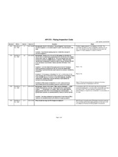
8 : In Section it is not clear what piping to include when calculating the inlet pressure drop for safety valves installed downstream of pressure -reducing valves. I have seen considerable technical debate on the topic but no final 1: When a safety valve is installed downstream of a pressure -reducing valve and where the relief scenario being considered is a blocked-in downstream system ( the only flow is that through the safety valve itself) should the 3% inlet pressure drop criterion be applied only to the safety valve inlet branch or should it be applied to all the pipework from the pressure -reducing valve exit flange to the safety valve inlet flange?Question 2: The safety valve capacity will always be greater than the maximum capacity of the pressure reducing valve. The pipework will offer minimal buffer volume between the two valves and so rapid opening/closing of the safety valve can be expected.
9 Would you recommend using a modulating valve on such systems (provided that the fluid is clean) and, if so, would the 3% criterion be applied to the maximum capacity of thereducing valve?Question 3: Even where a modulating valve is not used, the maximum sustainable flow will be determined by the size of the reducing valve. Would it be permissible to apply the 3% criterion to this flow rather than the safety valve rated capacity?Reply 1: The intent of is that all of the piping between the pressure source and the pressure relief valve should be considered for the inlet pressure drop calculations. Section specifically addresses the case for a process line attached to a pressure vessel with a relatively large reservoir of fluid. The user is cautioned that additional dynamic analysis may be required for the instance of a pressure relief valve downstream of the pressure reducing valve.
10 Reply 2: API does not provide consulting on specific engineering problems or on the general application of its standards . Technical inquiries submitted to API must be limited requests for an interpretation of the requirements in a Standard , or to the consideration of revisions based on new data or technology. We recommend you seek the assistance of a consultant or engineering company familiar with the requirements of the 3: See Reply Part I7th - Jan. : RP 520, Part I, Section requires the upstream condition be taken into account when calculating the required area of a relief valve in a two-phase flashing flow application. There is no consideration for the portion of the inlet liquid that flashes through the relief valve during : Should the downstream condition also be considered when sizing for a two-phase flashing flow application?Although several of the equations presented in Appendix D allow calculation of the required area of the relief device using only properties of the fluid at the inlet conditions, the two-phase methodology does take into consideration the effect of liquid that flashes across the valve.