Transcription of APOLLO AE-SERIES ELECTRIC ACTUATORS
1 APOLLO AE-SERIES ELECTRIC ACTUATORSG eneral Installation, Operation, Specifications, Maintenance and Trouble Shooting InstructionsThe following is intended as a guide only in installing and operating the ELECTRIC actuator . Themanufacturer assumes no liability whatsoever for any personal injury or other special or consequentialdamages that may occur. There are no warranties as to suitability for a specific application or / Mechanical Operation Verify that the valve breakaway torque is less than the rated output torque of the actuator . Any mechanical stops that would interfere with the operation of the actuator must be removedbefore installation of the actuator , lever, travel stops, etc.
2 The actuator output coupling must be centered with the valve stem to prevent side loading, whichcauses premature stem packing wear. The AE-SERIES actuator is not recommended for actuation of butterfly valves or other similarresilient seated valves, unless installed with Motor Break option. To use the manual override feature (identified on cover label), the override shaft must be presseddown firmly at least 1/4 in order to disengage the motor from the gears. The manual override isnot designed to overcome torque in excess of the rated torque of the actuator . Serious damageto the gear system may result from excessive turning force on the manual override.
3 The AE-SERIES actuator may be mounted in any position, horizontal, upside down. If theconduit entrance points upward, conduit piping must be oriented as to prevent condensation fromentering the actuator from the conduit Operation Always verify that the supply voltage and required voltage are the same. AE-SERIES 24 VAC, 115 VAC and 230 VAC ACTUATORS use capacitor run-reverse induction motors,which create higher feedback voltages that the supply voltage. Control devices connected toterminals 3 and 4 must be rated for 250 VAC minimum for 15 VAC ACTUATORS , (440 VAC min. for230 VAC ACTUATORS : 125 VAC min.)
4 For 24 VAC). Do not wire ACTUATORS in series or parallel with another actuator or other electrical equipment dueto the induction feedback voltage created by the motor. Separate (isolated contacts) are required for each actuator . When wiring DC voltage ACTUATORS , verify that terminal polarity is correct (pos.+ & ). Failureto do so will cause the actuator to operate out of its normal 90 degree rotation. The AE-SERIES ACTUATORS are designed to operate at 25% duty cycle at temperatures below100 F. This means that for a cycle time of 25 seconds the actuator must rest for 75 is an average.
5 For example: The actuator may cycle several times in a row, but must restfor a period 75% longer that the time it operated. All models require electrical power to both OPEN and to CLOSE the actuator and normal circumstances the actuator will not require additional lubrication. All of the actuator sessential components are permanently lubricated at the factory. Seal conduit entrances to prevent water or dirt from entering the housing. Excessive moisturecan cause premature wear or corrosion within the housing. Periodically inspect actuator and valve assembly for worn parts, loose fasteners, or damage tothe outside of the SpecificationsAmperage Draw (max.)
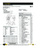
6 Starting or locked rotor current voltageActuatorModelBreakawayTorqueOutpu t( )CycleTime90 Travel(50%Load)DutyCycle*24 VAC115 VAC230 VAC12 VDC24 VDCAE200200 : 90 Travel = Travel From Closed position to Open position or vice versa. * Duty Cycle for 24 VAC will be approximately 20%.MotorAC models: 24 VAC, 120 VAC or 230 VAC, Reversible. 3 wire,capacitor run. Self-resetting thermal overload protection, ClassB insulation, sub-fractional models: 12 VDC or 24 VDC, Reversible. 2 wire, POS. &NEG. No thermal overload (external circuit breaker or fusesuggested for protection).
7 LubricationPermanently lubricated gear train and CycleThe AE-SERIES ACTUATORS are designed to operate at 25% dutycycle at temperatures below 100 F. See Electrical Operating Range32 F to 150 F standard-40 F to 150 F with optional heater & thermostatThermal ProtectionSelf-resetting (AC Motors Only)Conduit Connections(2) 1/2 -NPT femaleDirection Of TravelClockwise to Close, Counterclockwise to Open (Positionindicator shaft only, manual override shaft rotates opposite) AE-SERIES NUMBERING SYSTEMC onstantTorqueVoltageOptions2001 = 115 vac0 = Standard4002 = 24 vacA = One extra switch & cams6003 = 220 vacB = Two extra switches & cams8004 = 12 vacC = Three extra switches & cams10005 = 24 vacD = Heater & ThermostatE = Single PotentiometerEnter all digits ofTorque valueF = Motor BreakNote: AE will always be the first two characters of the part number, all digits from torque value must be entered into part number( 400, 1000 etc.)
8 Only use one digit for voltage depiction ( 1-5). For the options listing you may use more than one character,up to three ( 0, AD or BD etc.).24/115/230 VAC Wiring DiagramSUGGESTED CONTROL WIRING (CUSTOMER SUPPLIED). POSITIION INDICATOR JUNCTION 1-2 AND 1-5.(CUSTOMER SUPPLIED).115 VAC LINE VOLTAGECLOSED POSITION SWITCH (TOP)OPEN POSITION SWITCH (BOTTOM)OPTIONAL MOTOR RREAKTERMINALS 6-12 ARE USED FOR OPTIONAL LIMIT SWITCHES OR HEATER & THERMOSTATOPTIONAL 15 WATT 115 VAC HEATER & THERMOSTATLINE VOLTAGEW1W2F1 OPTIONAL24 VAC 60 HZ 1 PHREDBLUE5 AMP115 VAC 60 HZ 1 PHREDBLUE1 AMP230 VAC 60 HZ 1 AMPDUE TO HIGH AC INDUCTION FEEDBACK VOLTAGE THROUGH THE CAPACITOR ANDTERMINALS 3 & 4, MULTIPLE ACTUATORS CANNOT BE WIRED IN PARALLEL.
9 SEPARATERELAYS (ISOLATED CONTACTS) MUST BE PROVIDED FOR EACH actuator . DEVICESCONNECTED TO TERMINALS 3 & 4 MUST BE RATED FOR 250 VAC OR (440 VAC FOR 230 VACOPERATION VOLTAGE).12/24 VDC WIRING DIAGRAMON-OF-ON DPDT CONTROL WIRING (CUSTOMER SUPPLIED)(CUSTOMER SUPPLIED).115 VAC LINE VOLTAGECLOSED POSITION SWITCH (TOP)RED +TERMMOTOR TERM BLACKOPEN POSITION SWITCH (BOTTOM)TERMINALS 6-12 ARE USED FOR OPTIONAL LIMIT SWITCHES OR HEATER & THERMOSTATOPTIONAL 15 WATT 115 VAC HEATER & THERMOSTATLINE VOLTAGEW1W2F1 OPTIONAL12 VDCORANGEBLUE3 AMP24 AMPMANUAL OVERRIDE SHAFT .312 SQUARECPTIVE SCREWS ARE 1/4 20 UNC SOCKET HEAD CAP SCREWS, 6 PLACESINDICATOR SHOWN IN CLOSED POSITION1/2 NPT, TYPICAL BOTH CLEARANCE (FROM TOP OF OVERRIDE SHAFT) REQUIRED FOR COVER REMOVAL5/16-18 UNC X.
10 62 DEEP4 PLACES X .87 SQUAREMOUNTING PATTERN ISO 5211 F07AE- series DIMENSIONS