Transcription of Applications Engineering Manual - Trane
1 November 2011 SYS-APM001-ENApplications Engineering ManualChiller System Design and ControlChiller System Design and ControlSusanna Hanson, Applications engineer Mick Schwedler, Applications manager Beth Bakkum, information designer 2009 Trane All rights reservedChiller System Design and ControlSYS-APM001-ENTrane, in proposing these system design and application concepts, assumes no responsibility for the performance or desirability of any resulting system design. Design of the HVAC system is the prerogative and responsibility of the Engineering professional. Trane and the Trane logo are registered trademarks, and TRACE, System Analyzer and TAP are trademarks of Trane , a business of Ingersoll-Rand.
2 PrefaceThis Manual examines chilled - water -system components, configurations, options, and control strategies. The goal is to provide system designers with options they can use to satisfy the building owners desires, but this Manual is not intended to be a complete chiller-system design designers may get the most use from this Manual by familiarizing themselves with chilled - water -system basics and understanding the benefits of various options. Thereafter, when a specific job will benefit from these advantages, consult appropriate sections of the Manual in Engineers Newsletters that are referenced in this Manual are available at: System Design and Controliii ContentsPreface.
3 IPrimary System Components .. 1 Chiller .. 1 Loads .. 7 chilled - water Distribution System .. 10 Condenser- water System .. 13 Unit-Level Controls .. 15 Application Considerations .. 18 Small chilled - water Systems (1-2 chillers) .. 18 Mid-Sized chilled - water Systems (3-5 Chillers) .. 21 Large chilled - water Systems (6+ Chillers, District Cooling) .. 22 Chiller Plant System Performance .. 24 System Design Options .. 27 Condenser- water temperatures .. 29 chilled - and Condenser- water Flow Rates .. 29 Cost Implications .. 38 Misconceptions about Low-Flow Rates .. 39 System Configurations .. 42 Parallel Chillers.
4 42 Series Chillers .. 44 Primary Secondary (Decoupled) Systems .. 45 Variable-Primary-Flow Systems .. 55 chilled - water System Variations .. 70 Heat Recovery .. 70 Condenser Free Cooling or water Economizer .. 70 Preferential Loading .. 73 Series Counterflow Application .. 77 Unequal Chiller Sizing .. 78 System Issues and Challenges .. 79 Low T Syndrome .. 79 Amount of Fluid in the Loop .. 79 Contingency .. 81 Alternative Energy Sources .. 82 Plant Expansion .. 83 Retrofit Opportunities .. 84 Applications Outside the Chiller s Range .. 84ivChiller System Design and ControlSYS-APM001-ENSystem Controls.
5 87 chilled - water System Control .. 87 Condenser- water System Control .. 89 Failure Recovery .. 94 Conclusion .. 96 Glossary .. 97 References .. 100 Index .. 103 SYS-APM001-ENChiller System Design and Control1 Primary System ComponentsChilled- water systems consist of these functional parts: Chillers that cool the water or fluid Loads, often satisfied by coils, that transfer heat from air to water chilled - water distribution pumps and pipes that send chilled water to the loads Condenser- water pumps, pipes, and cooling towers or condenser fans that reject heat from the chiller to ambient air Controls that coordinate the operation of the mechanical components together as a systemIn most cases, the chiller s purpose is to make water colder.
6 Some chillers cool a mixture of water and other chemicals, most commonly added to prevent freezing in low-temperature Applications . Other additives may be used to modify the properties of the fluid, thereby making it more suitable for its intended application. For the purposes of this Manual , the term water can be understood to be any such acceptable fluid, with recognition of the diverse Applications in which chillers are used. The chiller rejects the heat extracted from the chilled water , plus the heat of compression (in the vapor-compression cycle), or the heat of absorption (in the case of an absorption chiller) to either the ambient air (air-cooled) or to another circuit of water ( water -cooled).
7 If the compressor-motor is refrigerant cooled, the chiller also rejects heat generated by motor inefficiency. Air-cooled condensers use fans to facilitate cooling by the ambient air. water -cooled condensers typically use an evaporative cooling tower. After the water has been chilled , it is distributed via pumps, pipes, and valves (the distribution system) to the loads, where a heat exchanger for example, a cooling coil in an air-handler transfers heat from the air to the chilled water , which is returned to the chiller. Each component of the chilled - water system is explained in more detail in the following are a variety of water chiller types. Most commonly, they are absorption, centrifugal, helical rotary, and scroll.
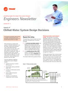
8 Some reciprocating chillers are also available. Chillers can be either air- or water -cooled. Major vapor-compression chiller components include an evaporator, compressor(s), condenser, and expansion device(s) (Figure 1). This Manual discusses the chiller s evaporator and condenser and their relationship to the chilled - water more details on the basic operation and components of a chilled - water system, consult another Trane publication, chilled - water Systems, part of the Air Conditioning Clinic Systems Series (TRG-TRC016-EN). Specific application considerations for absorption chillers are addressed in another Trane publication, Absorption Chiller System Design (SYS-AM-13).
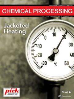
9 2 Chiller System Design and ControlSYS-APM001-ENPrimary System ComponentsFigure 1. Typical vapor-compression chillerWater-cooled chillers are typically installed indoors; air-cooled chillers are typically installed outdoors either on the roof or next to the building. In cold climates, air-cooled chillers may have a remote evaporator inside the building for freeze protection. Chiller evaporatorThe evaporator section of a water chiller is a shell-and-tube, refrigerant-to- water heat exchanger. Depending on the chiller s design, either the refrigerant or the water is contained within the tubes. In a flooded shell-and-tube evaporator (Figure 2), cool, liquid refrigerant at low pressure enters the distribution system inside the shell and moves uniformly over the tubes, absorbing heat from warmer water that flows through the 2.
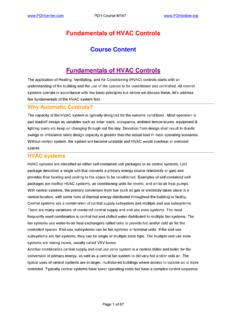
10 Flooded evaporator cut-awayCompressorCondenserEvaporatorTub e BundleLiquid Level SensorChilled water ReturnLiquid RefrigerantRefrigerant VaporChilled water SupplyPrimary System ComponentsSYS-APM001-ENChiller System Design and Control3 In a direct-expansion (DX) shell-and-tube evaporator (Figure 3), warmer water fills the shell while the cool, lower-pressure liquid refrigerant flows through the 3. Direct-expansion evaporator cut-awayIn either design, there is an approach temperature, which is the temperature difference between the refrigerant and exit water stream temperatures . The approach temperature is a measure of the heat transfer efficiency of the of chilled - water temperatureFor a given chiller, as the leaving chilled - water temperature drops, the refrigerant temperature and pressure must also drop.