Transcription of . ARml - Vintage Snow
1 THEORY Snovv111obile ~rive Syste111 . arml ~DTERPRISES,IDI. THIEF RIVER FALLS, MINNESOTA Fore\Nord The intent of this manual is to provide you, the service technician, with a detai led examination of the design, function, and operation of the drive system used on Arctic Cat snowmobiles. This information is provided to help you acquire a working knowledge of basic drive system theory and design as applied to snowmobiles. With this knowledge, you should be able to pro-vide the quality service the customer expects and deserves. Table of Contents Foreword .. Introduction Glossary Drive System Theory of Operation Drive Clutch Basics . Drive Clutch Engagement Speed Drive Clutch Maintenance Driven Clutch Basics Sprocket Ratio .. Drive Belt Basics .. Drive System Adjustments Modifications .. Gearing .. Summary of Drive System Components . 1.
2 2 . 3 4-6 7-8 .8- 12 . 13- 14 .. 14 .15-16 17 18 19 19 20 20 1 Theory of Operation The drive system of a snowmobile is a major component in giving the operator maximum en-j oy ment and utility. To fully understand the im portant effect the drive system has on the per-formance of the Arctic Cat Snowmobile, each component and its function must be under-stood. In the sections that follow, elements of the driven clutch, drive clutch, drive belt and sprocket ratio will be examined. Knowing what influence the various elements have on the drive system will help you to better understand the operating characteristics of the "Arctic Cat System". Matching the Drive System to t he Engine Snowmobile powerplants are generally highly tuned 2-cycle engines and usually have a narrow band of operation. Depending upon the type of track used and the design of undercarriage, dif-ferent snow conditions produce different load resistances on the machine.
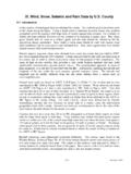
3 In order to give the operator maximum enjoyment and performance, the drive system should perform satisfactorily by delivering maximum power to t he track un-der all conditions and load demands. Before a drive and driven clutch can be matched correctly to an engine, the torque curve of the engine must be known, Fig. 11. Fig. 11 .. , ,, . l ~1 _,. l .. ! .. -i ,.. I I I ~ I I I I I I 1\ 30., =-'JL8~ !L / I'\ . !/ . v 1/ l ~' o; I ~~v /1 (JY r '\\\\\\\\\\\\\,\\\\ A (;,..,.-~, A.' l"ff,..T .-~ .. B '. u,.. ,.. HP ~2. 0 fT/165 < \\ 0'2U11 The t w o engines in the graph have the same amount of horsepower but at different rpm. Engine A : ft-lb at 6500 rpm = 38 hp Engine B: ft-lb at 9000 rpm= 38 hp The graph shows how different the torque curve of two engines can be at the same maximum hp (See A & B curves). Engine "B" develops much less torque but runs at a high rpm to produce the same hp.))
4 Engine A is a family machine type engine. En-gine B is a high performance racing engine. Be-fore the clutches can be matched, the torque curves must be known. From the torque curve, engine "A" has maximum hp at 6500 rpm whereas engine "B" has peak output at 9000 rpm. If the drive system is matched correctly, the engine will run at the rpm where the most hp is developed. This is the point that the engine should run at full throttle in all conditions. If the engine runs at either above or below the point of maximum hp, the clutches are not using optimum output of the engine. Example: (See Fig. 11) If the drive system on engine "B" was not matched correctly, and the engine ran at 10,000 rpm, what is the hp at the drive clutch? (Answer: The hp would drop from 38 hp down to hp, a loss of almost 8 hp because the rpm of the engine was past its peak power point).
5 Selecting t he Engagement Speed from the Tor-que Curve The desired drive clutch engagement speed is where t he engine puts out enough horsepower to move the snowmobile from a stop without hesi-tation o r a "flat spot". From the torque curve of the engine, the point at which the engine will not hesitate on engagement can be calculated. In the introduction, we said the driven clutch was used to multiply engine torque needed by the track to pull the snowmobile. The low end clutch ratio is 3. 79: 1. The drive clutch must turn revolutions before the driven clutch can turn 1. Therefore, the amount of engine tor-que is increased t imes when transmitted to the driven clutch at engagement. The sprocket ratio that the machine is using also multiplies the torque. If the gear rat io is 19:39, the sproc-ket ratio is :1. The torque through the sprockets will be times greater.
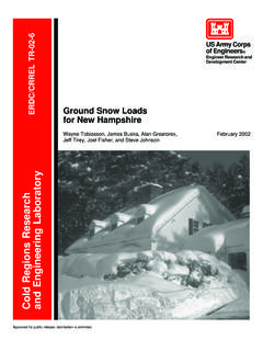
6 Example: From past testing we know that 110 ft-lb of torque-is needed at the track to move the snowmobile from a stop without hesitation. Question: At what engine rpm do we have 110 ft-lb of torque? (See Fig. 11 at torque curve). 7 Fig. 14 . onua Centrifugal Weights The second variable affecting drive clutch opera-tion is the clutch weights. The weights and rollers are bolted to the arms that are pinned to the spider. The spider has three arms: each arm has two weights and a roller and bushing that is retained to the arm by a small bolt and lock nut. The complete spider assembly (arms, weights, and rollers) is fastened to the stationary sheave shaft by three set screws and a split ring. I 10 F ig. 15 --The function of the weights is to p rovide an outward force against the spring while the rollers roll on the three ramps. When the engine is idling (less than clutch engagement rpm), the outward force is not enough to overcome the outward pressure of the spring.
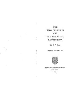
7 However, as en-gine rpm increases and predetermined clutch en-gagement speed is reached, the weights are thrown outward by centrifugal force caused by increased engine rpm. Since the outward move-~ ment of the weights overcomes the pressure of spring, the moveable sheave pushes the drive belt against the stationary sheave. Power is then transmitted from the drive clutch through the remainder of the drive system. The weights in the drive clutch affect the engine rpm throughout the complete shift pattern. Arc-tic makes available weights ranging from one gram to over 18 grams, Fig. 16. By increasing the weight, the centrifugal force is greater and the drive clutch will "shift up" quicker. Conversely, by putting on lighter weights, the force becomes less and the drive clutch takes longer to com-pletely "shift up". Fig. 16 WEIGHT CHART Part Gram No.
8 Weight Light 0146-227 0146-225 Q146-226 I 0146-159 0146-108 ' 0146-175 3 ..'73 . ).) [" 0146-135 ~ 0146-107 ql"'l 0146-279 \.. ) 0146-106 j 0146-278 , 0146-123 . ~ ~ -0146-105 ..,: . 0146-286 ~ 0146-136 0146-104 0146-166 .. -~ 4 . ,.~ . 0146-307 .. ~,;;.;-.,.-. ~ 1':. 0146-314 Heavy 0146-308 The clutch weiglits also ha'Ze a slight effect on engagement speed. A heavy weight slightly de-creases the drjve clutch engagement speed and produces .lower engine rpm throughout the shift pattern. By contrast1~a light weight slightly in-$ (eases engagemei}.t speed and produces higher engine rpm throughout the shift pattern. Fig. 16 . ' .. Outside Thickness . Color Diameter (inch) Code .400 .250 Aluminum .463 .250 Aluminum .521 .250 Aluminum .377 .250 White .406 .250 Yellow ..437 . 250 Red .471 .250 Black.]
9 500 .228 Green .491 .250 White / .511 .250 Bl ack .530 .250 Red .. 549 .250 Black .568 .250 Yellow ..598 .250 Black .629 .250 Red .644 .250 Green .665 .250 White .684 .250 Red .703 .250 Yellow . , ..723 .210 Black .873 .250 Green What Happe~s When the Clutch Weight are too Heavy or too Light for the Machine Being Clutched? From before, we know that each engine has an rpm where maximum horsepower is developed. For example: If engine A (see page 7) has maxi-mum horsepower at 6500 rpm, it should run 6500 rpm at full throttle. If the clutch weights were too heavy, the clutches would "shift up" too fast pulling the engine rpm below 6500. Thus, ma~imum ~J? would not be delivered from 11 /0 the .engine, causing a loss in speed and perfor-mance. If the clutch weights were too light, the clutches would not "shift up" t o the 1: 1 ratio and engine rpm would be over 6500.
10 With too light a weight, the rpm would run over t he point of maximum power, causing a loss in speed and performance. NOTE: When the proper weights are used in the drive clutch, the engine will run at the rpm where maximum hp is delivered. The clutches will shift from low ratio (engagement) to high ratio (top speed) at the fastest rate they can without going either above or below the point of maximum power. Ramps The third variable affecting drive clutch opera-tion is the clutch ramp. Drive clutch ramps made by Arctic Cat are carefully designed to provide the proper shift pattern for a specific engine. The total shift pattern of the drive clutch is af-fected by the clutch ramps. The ramps are de-signed so clutch engagement is smooth, and the total shift pattern is responsive to various loads. The design of the ramp is dependant upon the torque curve of the engine.