Transcription of ARTICLE 250 GROUNDING AND BONDING
1 Mike Holt Enterprises ( )55 ARTICLE250 GROUNDING AND BONDINGI ntroduction to ARTICLE 250 GROUNDING and BondingNo other ARTICLE can match ARTICLE 250 for misapplication, violation, and misinterpretation. Terminology used in this ARTICLE has been a source for much confusion, but that s improved during the last few NEC revisions. It s very important to understand the difference between GROUNDING and BONDING in order to correctly apply the provisions of ARTICLE 250. Pay careful attention to the definitions that apply to GROUNDING and BONDING both here and in ARTICLE 100 as you begin the study of this important ARTICLE . ARTICLE 250 covers the GROUNDING requirements for providing a path to the earth to reduce overvoltage from lightning, and the BONDING requirements for a low-impedance fault current path back to the source of the electrical supply to facilitate the oper-ation of overcurrent protection devices in the event of a ground the past several Code cycles, this ARTICLE was extensively revised to organize it better and make it easier to understand and implement.
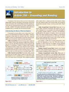
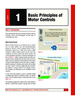
2 It s arranged in a logical manner, so it s a good idea to just read through ARTICLE 250 to get a big picture view after you review the definitions. Next, study the ARTICLE closely so you understand the details. The illustrations will help you under-stand the key I. ScopeArticle 250 contains the following GROUNDING and BONDING requirements:(1) What systems and equipment are required to be grounded.(3) Location of GROUNDING connections.(4) Types of electrodes and sizes of GROUNDING and BONDING conductors.(5) Methods of GROUNDING and DefinitionBonding Jumper, Supply-Side. The conductor on the supply side of the service or separately derived system overcurrent protection device that ensures electrical conductivity between metal parts and the grounded conductor. }Figure 250 1, }Figure 250 2, and }Figure 250 3 SCH 80 BONDING Jumper, Supply-Side, DefinitionSupply-SideBonding JumperCopyright 2017, theserviceovercurrentprotectiondevicetha tensureselectricalconductivitybetweenmet alpartsrequiredto beconnected.
3 }Figure 250 1 Mike Holt s Illustrated Guide to Understanding 2017 NEC Requirements for BONDING and GROUNDING | GROUNDING and BondingAuthor s Comment:n System GROUNDING helps reduce fires in buildings as well as voltage stress on electrical insulation, thereby ensuring longer insulation life for motors, transformers, and other system components. }Figure 250 5 Note 1: To limit imposed voltage, the GROUNDING electrode conductors shouldn t be any longer than necessary and unnecessary bends and loops should be avoided. }Figure 250 6 Performance Requirements for GROUNDING and BONDING (A) Solidly Grounded this QR code for a video of Mike explaining this topic; it s a sample from the DVDs that accompany this textbook.(1) electrical System GROUNDING . electrical power systems are grounded (connected to the earth) to limit the voltage induced by lightning, line surges, or unintentional contact by higher-voltage lines.
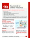
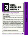
4 }Figure 250 4 2017 CCTransformerTransformerDisconnectCopyri ght 2017, :EquipmentGroundingConductor:GroundingEl ectrodeConductorGEC: SystemBondingJumperSBJ:Supply-SideBondin gJumperSSBJN:NeutralLegendTheconductoron thesupplysideof theseparatelyderivedsystemovercurrentpro tectiondevicethatensureselectricalconduc tivitybetweenmetalpartsrequiredto Jumper, Supply-Side, Definition}Figure 250 2 electrical System (A)(1)Electricalpowersystemsaregrounded( connectedtotheearth)tolimitthevoltageind ucedbylightning,linesurges,or 2017, }Figure 250 4 TransformerDisconnectTransformerDisconne ctPanelCopyright 2017, System (A)(1) CommentSolidly Grounded SystemSystemgroundinghelpsreducefiresin buildingsaswellasvoltagestressonelectric alinsulation,therebyensuringlongerinsula tionlifeformotors,transformers, :EquipmentGroundingConductor:GroundingEl ectrodeConductorGEC: SystemBondingJumperSBJ:Supply-SideBondin gJumperSSBJN:NeutralLegend}Figure 250 5 GECSBJSBJEGCEGCEGCNNNNS ervicePanelboardGenerator ()SDSGen.
5 DisconnectTransfer SwitchCopyright 2017, Jumper, Supply-Side,SDS, DefinitionTheconductoronthesupplysideof theSDSovercurrentprotectiondevicethatens ureselectricalconductivitybetweenmetalpa rtsrequiredto :EquipmentGroundingConductor:GroundingEl ectrodeConductorGECMBJ:MainBondingJumper :SystemBondingJumperSBJ:Supply-SideBondi ngJumperSSBJE ffectiveGround-FaultCurrentPath}Figure 250 3 Mike Holt Enterprises ( )57 GROUNDING and BONDING | s Comment:n GROUNDING metal parts helps drain off static electricity charges before flashover potential is reached. Static GROUNDING is often used in areas where the discharge (arcing) of the voltage buildup (static) can cause dangerous or undesirable condi-tions [ Note 3].(3) Equipment BONDING . Metal parts of electrical raceways, cables, enclosures, and equipment must be connected to the supply source via an effective ground-fault current path. }Figure 250 9 Note 2: See NFPA 780, Standard for the Installation of Lightning Protection Systems for GROUNDING and BONDING of lightning protection systems.
6 (2) Equipment GROUNDING . Metal parts of electrical equipment are grounded to reduce arcing within the buildings/structures from induced voltage from indirect lightning strikes. }Figure 250 7 DANGER: Failure to ground metal parts to earth can result in induced voltage on metal parts from an indi-rect lightning strike seeking a path to the earth within the building possibly resulting in a fire and/or electric shock from a side flash. }Figure 250 8 TransformerDisconnectTransformerDisconne ctPanelCopyright 2017, System (A)(1) Note 1 Tolimitimposedvoltage,thegroundingelectr odeconductorsshouldn :EquipmentGroundingConductor:GroundingEl ectrodeConductorGEC: SystemBondingJumperSBJ:Supply-SideBondin gJumperSSBJN:NeutralLegend}Figure 250 6 SeparateBuildingServiceEquipment Grounded to (A)(2)Copyright 2017, electricalequipmentmustbegroundedto reducearcingwithinthebuildings/structure sfrominducedvoltagefromindirectlightning .
7 }Figure 250 7 Equipment (A)(2) CommentCopyright 2017, highvoltagefromanindirectlightningstrike seekingapathtotheearthwithinthebuilding, possiblyresultinginafireand/orelectricsh ock.}Figure 250 8 MeterX1X2X0 MainOutletLoadPanelSourceGroundFaultMBJN NEGCC opyright 2017, Ground-FaultCurrent PathEGC:EquipmentGroundingConductorGEC:G roundingElectrodeConductor:MainBondingJu mperMBJN:NeutralConductorLegendGECB onding of electrical (A)(3)Metal parts of electrical raceways, cables, enclosures,and equipment must be connected to the supply sourcevia an effective ground-fault current path.}Figure 250 9 Mike Holt s Illustrated Guide to Understanding 2017 NEC Requirements for BONDING and GROUNDING | GROUNDING and BONDING (5) Effective Ground-Fault Current Path. Metal parts of electrical race-ways, cables, enclosures, or equipment must be bonded together and to the supply source in a manner that creates a low-impedance path for ground-fault current that facilitates the operation of the circuit over-current protection device.
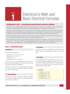
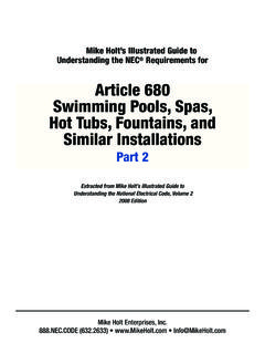
8 }Figure 250 13 Author s Comment:n To ensure a low-impedance ground-fault current path, all circuit conductors must be grouped together in the same raceway, cable, or trench [ (B), (I), and (A)]. }Figure 250 14 Author s Comment:n To quickly remove dangerous voltage on metal parts from a ground fault, the effective ground-fault current path must have sufficiently low impedance to the source so fault current will quickly rise to a level that will open the branch- circuit overcurrent protection device. }Figure 250 10 n The time it takes for an overcurrent protection device to open is dependent on the magnitude of the fault current. A higher fault current value will result in a shorter clearing time for the overcurrent protection device. For example, a 20A overcurrent protection device with an overload of 40A (two times the 20A rating) takes 25 to 150 seconds to open. The same device at 100A (five times the 20A rating) trips in 5 to 20 seconds.
9 }Figure 250 11 (4) BONDING Conductive Materials. Electrically conductive materials likely to become energized, such as metal water piping systems, metal sprinkler piping, metal gas piping, and other metal-piping systems, as well as exposed structural steel members, must be connected to the supply source via an effective ground-fault current path. }Figure 250 12 Author s Comment:n The phrase likely to become energized is subject to inter-pretation by the authority having 100 Aovercurrent device quickly opens andremoves dangerous voltage from metal ft ohmsFault Current =E=120V= ohms200 ft ohms100 ADeviceOpening an Overcurrent DeviceEGCSSBJSBJC opyright 2017, :EquipmentGroundingConductor: SystemBondingJumperSBJ:Supply-SideBondin gJumperSSBJL egend}Figure 250 10 100 AFaultClears in5 to 20 Seconds40 AFaultClears in25 to 150 Seconds40A5 Sec10 Sec15 Sec20 Sec25 Sec30 Sec35 Sec40 Sec45 Sec145 Sec150 Sec155 Sec100 ATime-Current Curve20 AInverseTime BreakerThe higher the current, the faster the fault 2017, }Figure 250 11 BONDING Electrically Conductive (A)(4)MCompressedAirWater PipingONOFFINTERRUPTINGRATINGMAXAMPS.
10 , PipingSprinkler PipingWARNINGArc Flash and Shock HazardAppropriateRequiredPPEA vailable Fault Current:Installation Date:01/01/20119,500 AmpsNormally noncurrent-carrying electrically conductivematerials likely to become energized must be bondedto an effective ground-fault current 2017, }Figure 250 12 Mike Holt Enterprises ( )59 GROUNDING and BONDING | : What s the maximum fault current that can flow through the earth to the power supply from a 120V ground fault to metal parts of a light pole without an equipment GROUNDING conductor that s grounded (connected to the earth) via a rod having a contact resistance to the earth of 25 ohms? }Figure 250 16 Solution: I = E/R I = 120V/25 ohmsI = : the earth isn t a low impedance path for fault current, it isn t suitable to serve as the required effective ground-fault current path, therefore an equipment GROUNDING conductor of a type recognized in is required to be installed with all circuits.