Transcription of As data transmission speeds increase, separation …
1 20 | advancing information transport systems | telecommunications cables are routed next to large electromagnetic fields, surplus voltage and current can be induced on them. If the power level of the electrical cable is large enough, the electrical noise can interfere with operation and performance of the telecommunications applications running on the cabling. Electrical and data systems designers must be familiar with this phenomenon and ensure that the two systems can work in harmony. For analog voice communication, electromagnetic interference (EMI) can create psophometric noise, which degrades transmission quality. In data communication, excessive EMI reduces the ability of distant receivers to effectively detect data packets.
2 The result of this inability to detect data packets is an increase in network congestion and network traffic as a result of errors and due to packet retransmissions. Sources of Coupling Between Electrical and data Cables The coupling between power lines and telecommunications cables may be a result of one or more of the following types of coupling conductive, capacitive or inductive coupling. Conductive coupling is the transfer of energy by means of physical contact. This type of coupling is also known as direct coupling. In a commercial and industrial facility cabling installations, the incidence of conductive coupling is typical when the grounding and bonding systems utilized for power and telecommunications systems are not appropriately isolated from each other.
3 Capacitive coupling is the transfer of energy from one circuit to another by means of mutual capacitance between circuits. This coupling can be intentional or accidental. Capacitive coupling can develop between telecommunications and power cables that run in parallel for long lengths through a building or other structure. The capacitance between two cables or conductors is caused by coupling between the power and data circuits. The value of the capacitance will vary with and depend upon the distance between the power and data circuits. The value of this capacitive coupling will be less for large distances and more for short distances. To reduce the voltage noise level from the capacitive coupling between cables, either the impedances can be increased or the capacitance can be decreased.
4 Screened twisted-pair cabling (ScTP) can be utilized to shield the cables from the circuit with the noise. This screening of the cable will reduce the value of capacitance. For situations where it is not an option to increase the impedance or decrease the capacitance, screened cabling may be the only option. Inductive coupling refers to the transfer of energy from one circuit component to another through a shared magnetic field. A change in the current flow through one conductor or cable can induce a current to flow in another conductor or cable. This coupling may be intentional or unintentional. The common building transformer works based on this type of coupling.
5 When current flows in a circuit while feeding a load in the system , it develops a magnetic flux proportional to As data transmission speeds increase , separation of power and data cables is more critical. BY kEITH LANED etermining the Appropriate separation of data and Power CablesFeature22 | advancing information transport systems | current that is flowing in the circuit. This magnetic flux may induce noise voltage into a nearby conductor. This can result in a current in the data or voice circuit. This type of coupling is very common between data and power conductors in commercial facilities. The layout of the conductors and the space between two cables establishes the strength of the inductive coupling.
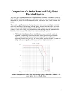
6 The use of metallic or nonmetallic raceway or cable tray or other pathways can affect the amount of induced fields that affects the data or voice cables. The strength of the magnetic field is directly proportionate to the current in the disturbing cable and inversely proportionate to the distance between the telecommunications and power cables. As illustrated in the examples below, power cables with higher power levels (kilovolt-ampere [kVA]) will require greater separation between voice and data cables. In order to minimize the effect of inductive coupling between circuits, it is essential to safeguard cable geometry for the complete cable length and to keep adequate separation between power and data cables.
7 Design for Proper separation of Cables When considering the effects from interference between power and data cables, electrical and data system designers must consider all of these effects together. This combined effect comes from conductive, capacitive and inductive coupling. These combined effects can be very destructive to data and voice signals Providing the proper separation between electrical and data systems is essential. Too little separation and the 60 hertz (Hz) noise from the electrical system can effect the transmission of the data signals. The project could be impacted significantly on the cost side from too much separation . There are many sources for a designer or engineer to identify the appropriate separation between the electrical and the data systems.
8 The two main sources should be the National Electrical Code (NEC ) and BICSI s Telecommunications Distribution Methods Manual (TDMM). The TDMM references standards from ANSI, TIA and EIA. ANSI/TIA/EIA 569-A indicates that the installed separation of both the telecommunications cable and the electrical cable should be governed by the applicable electrical safety code. The NEC (NFPA 70), Article (2005 NEC) indicates the separation requirements. Thissection of the NEC specifies the following: Communica-tion wires and cables shall be separated at least 50 mm (2 in) from conductors of any electric, power, Class 1, nonpower limited fire alarm, or medium power network powered broadband communication circuits.
9 Two exceptions are noted in the NEC:Exception #1: Where either (1) all of the conductors of the electrical light, power, Class 1, nonpower limited fire alarm and medium power network powered broadband communications circuits are in a raceway or in metal sheathed, metal clad, nonmetallic sheathed, type AC, or type UF cables, or (2) all of the conductors of communications cable are encased in #2: Where the communications wires and cables are permanently separated from the conductors of electrical light, power, Class 1, nonpower limited fire alarm, and medium power network power broadband communications circuits by a continuous and firmly fixed nonconductor such as porcelain tubes or flexible tubing, in addition to the insulation of the wire.
10 Electrical and data system designer and engineers should remember that NEC is primarily written for safety purposes; it is not intended to make recommendations for optimum performance of communication systems. The 50 mm (2 in) separation should be viewed as a safety issue only, not driven by performance issues of the sensitive data systems. There are many excerpts about how important separation is. Network cable solutions supplier Siemon recommends the following separation for pathways and spaces based on the power levels of the power Twisted-Pairn For less than 3 kVA: 50 mm (2 in) for pathways and 50 mm (2 in) for spacesn For > 3 < 6 kVA: m (5 ft) for pathways and 3 m (10 ft) for spacesn For > 6 kVA: 3 m (10 ft) for pathways and 6 m (20 ft) for spacesScreened and Shielded Cables n For less than 3 kVA: 0 mm (0 in) for pathways and 0 mm (0 in) for spacesn For > 3 < 6 kVA: m (2 ft) for pathways and m (2 ft) for spacesn For > 6 kVA.