Transcription of Autogard Torque Limiter 200 Series
1 Autogard Torque Limiter 200 SeriesAutogard Torque Limiter 200 Series Overview2 Autogard Torque Limiter 200 Series For more than 80 years, Autogard products have led the industry in overload protection with high-quality products, design innovation and production. Autogard products are manufactured to meet ISO 9001 using the latest machine tools and high-quality like a mechanical fuse to protect the weakest member of the drive train, the most effective location for Autogard Torque limiters is as close as possible to the component being protected. The 200 Series is a robust mechanical device that will disengage at a preset Torque value. The trip Torque is set above the normal startup and operating Torque , but below a Torque setting that would normally damage the driving and/or driven equipment.
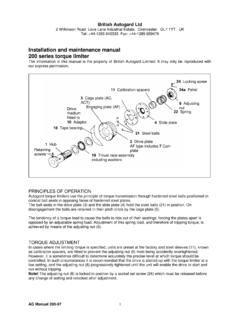
2 In the event of a jam, the 200 Series eliminates the threat of damage by disconnecting the inertia in the drive train. In the normal drive condition, Torque is transmitted through the drive balls A which are seated in detents in the drive plate B and the slide plate C , These are all held together under pressure from spring D .Disengagement on OverloadWhen the driven machine either jams or an overload occurs that is greater than the Torque setting, the balls roll out of their seats and force apart the drive plate B and the slide plate C . The balls are retained by the cage plate E and roll freely on the flat surface of the drive plate B and slide plate C .Re-engagementRe-engagement occurs in one of three ways depending upon which reset type is AC Automatic Random ResetThe ball detents in the drive plate B and the slide plate C , as well as the retaining holes in cage plate E are equally spaced on the same pitch circle diameter so that the balls will roll into the next detents after tripping in either direction.
3 Immediate shutdown is required to prevent wear of the ACT Automatic Single Position ResetThe ball detents are positioned in a scattered pattern so that the balls must return to their original position before they can reset. Re-engagement will occur within two revolutions in either direction. Immediate shutdown is required to prevent wear of the AF Free Wheeling DisengagementAs with Type AC, the detents in drive plate B and slide plate C are equally spaced. The retaining holes in the engagement plate E are elongated so that, as the balls roll from the detents, they can follow a cam profile onto a different running track away from the detents. Type AF can run at higher speeds as the balls will not ratchet in the detents.
4 Resetting is achieved by manually locking the plates and reversing the above correspond to paragraphs on the left and ACType ACTType AFFigure 2 Figure 13 Features and Benefits: Proven design with thousands of units successfully in operation Accurate Torque limitation prevents costly downtime Cost-effective design Standard designs can accommodate large Torque ranges Instantaneous disengagement protects equipment from damaging inertias Bi-directional protection Easy to adjust to desired allowable Torque Three reset types offered: - Type AC Automatic Random Reset - Type ACT Automatic Single Position Reset - Type AF Freewheeling, Manual Reset for high speeds Wide range of mounting configurations ensures the right solution for any problem: - Timing, HTD and V-Belt drives - Chain and sprocket drives - Gear drives - Flexible or rigid couplings - Flywheel or large gear mountingSelection: Data required for Torque Limiter selection: Application details for service factors Kilowatt (kW) and rpm of the driver Shaft details of the driving and driven equipment(1) Calculate the nominal Torque .
5 Torque (Nm) = Kw x 9550 / rpm Consideration should then be given to start Torque or other special circumstances depending on the position chosen in the drive system. Choose a set Torque with a suitable margin over nominal. Select the Torque Limiter which has a higher Torque rating.(2) Check limiting conditions: (a) Check hub bore capacity(b) Check the Torque Limiter dimensions such as the overall length and outside diameter(3) Select and specify the appropriate drive medium or 200 Series units may be supplied from the factory at a pre-set Torque and with the required drive medium assembled to the unit. Example: 205-5 / AC / S1-60mm / S2-90mm Refers to Model 205, Size 5, Automatic Random Reset S1 Bore = 60mm S2 Bore = 90mmAlso specify setting Torque is specifications contained within this brochure are correct at the time of going to print.
6 Rexnord is continually reviewing and updating the specifications on its entire Autogard product offering and therefore reserve the right to change any detail. Ordering the 200 Series Torque Limiter When ordering, please provide the following designation: Model and Size / Type / S1 bore / S2 bore Standard bore tolerance = H8 + normal fit key 4 Model 221 Size TorqueSpeedMassKgMass Moment of Inertia MR2 Kgm2 Type AC or AFNmType ACTNmType ACrpmType ACTrpmType AFrpm11-443-692005002, , , ,130113-1,7742005002, ,540158-2,9372005002, ,6271,130-8, Bore S1 mm DmmEmmMin. GmmMax. GmmJmmKmmL mmMin. MmmMax. page 13, Table 19 for spring selection and Torque range with specific springs. Higher speeds may be allowed under certain conditions.
7 Please consult Rexnord. 5S is available in Type AC and ACT resets only. Weights and moments of inertia apply to maximum S1 bores and exclude sprockets, are furnished for clearance fit unless otherwise specified by customer. Please consult drive medium may be mounted onto the adapter with screws and dowels and must be bored to dimension M . The supplied bearing may then be press fitted into the drive medium. Finally, the bearing should then be bored to dimension G as N is depth of blind bore S1 as normally furnished, unless otherwise specified. For through-shaft applications or for weight reduction, through-bore can be furnished for an extra charge. The bore beyond depth N will be to a dimension larger than the finish bore of length N.
8 123122322 Figure 3 Table1 Table 2 See Page 12 Model 221, for use with sprockets, pulleys or gears. Supplied complete with bearing and suitable mounting Sprocket (No. of Teeth)Smallest Sheave Diameter mm3/8" pitch1/2" pitch5/8" pitch3/4" pitch1" pitch1191512--44226211715126733124201713 804-312521171095-413328221495S-604841312 30 SizeStandard Mounting Hole Patterns (Min. Diameters)Dowels (X)Screws (W)A (PCD)mmOmmNo. of dowelsDowel of ScrewsScrew Size1343M436382353M558383363M670634683M8 957556103M1013510063123M12205135 The diameter quoted is to the bottom of a V-sheave groove or to the inside diameter of the flange of a timing belt pulley.
9 For sprockets, the above information applies only to a single strand chain. For multiple strand chain. Bolt holes to be equally spaced on bolt circle diameter specified. Care must be taken not to drill into other mounting holes in mounting holes furnished for a standard price adder. Special mounting holes quoted upon request. Please consult Rexnord. Table 3 Table 4112121156 Model 202 Size TorqueSpeedMassKgMass Moment of Inertia MR2 Kgm2 Type AC or AFNmType ACTNmType ACrpmType ACTrpmType ,130113-1, ,540158-2, ,6271,130-8, Bore S1mmDmmEmmHmmJmmLmmM mmN / / page 13, Table 19 for spring selection and Torque range with specific speeds may be allowed under certain conditions. Please consult Rexnord.
10 Weights and moments of inertias apply to maximum S1 bores and exclude sprockets, is available in Type AC and ACT resets only. 123412334 Model 202 supplied with a sprocket, pulley or gear as an integral part of the unit to give the shortest overall are furnished for clearance fit unless otherwise specified by keys must be used for maximum bore 5S is supplied in two hubs can be supplied with dimension W increased to accommodate larger size drive D S1 M NJELSENSORPLATESee page 12, Table 18 for dimensions and movement on 4 Table 5 Table 7 Table 6 SizeSmallest sprocket (No. of Teeth)Smallest Pulley Diametermm3/8 pitch1/2 pitch5/8 pitch3/4 pitch1 pitch1161311--42224191614116733023191713 864-272219151155-403228221695S-493934262 611 The pulley diameter quoted is to the bottom of the V-sheave groove or the inisde diameter for the flange of the timing pulley.