Transcription of Installation and maintenance manual 200 series …
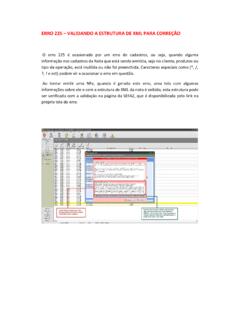
1 British Autogard Ltd 2 Wilkinson Road, Love Lane Industrial Estate, Cirencester, GL7 1YT, UK. Tel: +44-1285 640333 Fax: +44-1285 659476. Installation and maintenance manual 200 series torque limiter The information in this manual is the property of British Autogard Limited. It may only be reproduced with our express permission. 24 Locking screw 11 Calibration spacers 24a Pellet 5 Cage plate (AC, ACT) 6 Adjusting Engaging plate (AF) nut Drive medium 22 Spring fitted to 10 Adaptor 4 Slide plate 18 Tape bearing 21 Steel balls 3 Drive plate 1 Hub AF type includes 7 Cam Retaining plate screws 19 Thrust race assembly including washers PRINCIPLES OF OPERATION. Autogard torque limiters use the principle of torque transmission through hardened steel balls positioned in conical ball seats in opposing faces of hardened steel plates.
2 The ball seats in the drive plate (3) and the slide plate (4) hold the steel balls (21) in position. On disengagement the balls are retained in their pitch circle by the cage plate (5). The tendency of a torque load to cause the balls to ride out of their seatings, forcing the plates apart is opposed by an adjustable spring load. Adjustment of this spring load, and therefore of tripping torque, is achieved by means of the adjusting nut (6). TORQUE ADJUSTMENT. In cases where the limiting torque is specified, units are preset at the factory and steel sleeves (11), known as calibration spacers, are fitted to prevent the adjusting nut (6) from being accidently overtightened. However, it is sometimes difficult to determine accurately the precise level at which torque should be controlled.
3 In such circumstances it is recommended that the drive is started up with the torque limiter at a low setting, and the adjusting nut (6) progressively tightened until the unit will enable the drive to start and run without tripping. Note! The adjusting nut (6) is locked in position by a socket set screw (24) which must be released before any change of setting and relocked after adjustment. AG manual 200-97 1. CAUTION: It is important that the spring (22) is not over-tightened. If it is not free to deflect sufficiently to permit full tripping movement of the slide plate (4), the Autogard will be prevented from tripping. Table 2 gives the spring ratings and minimum operating lengths. RE-ENGAGEMENT AFTER TRIPPING (AC & ACT TYPES).
4 Types AC & ACT are automatic reset units and all that is required to re-engage the Autogard is to rotate the drive until the balls (21) roll into the next seat. The ACT units have staggered seatings on two or more pitch circles which provide a synchronous (timed) reset, always resetting in the same position. CAUTION: It is necessary to shut down the drive quickly after disengagement. Therefore, in all applications using the AC / ACT type Autogards it is recommended that a limit switch is fitted to sound an alarm and / or switch off the drive. The switch can be activated by the limit switch operating plate (12) supplied with each unit. RE-ENGAGEMENT AFTER TRIPPING (AF TYPE). Type AF ( manual re-engaging) units are fitted with a star shaped cam plate (7) screwed to the drive plate (3) and an engaging plate (5) instead of the cage plate.
5 On overload, the cam plate (7) forces the balls (21). radially outwards along the slots in the engaging plate (5). This ensures the drive balls run freely on a track outside the ball seatings and so prevent the unit resetting. To return them to the drive position, rotate either side of the unit until the slots in the periphery of the engaging plate (5) line up with slots in the drive plate (3). Lock the two plates in this position with any convenient tool (eg screwdriver or hexagonal key), and rotate them relative to the slide plate (4). If the correct direction of rotation is chosen, the balls will track inwards to engage with their seatings in the drive plate (3) after about 30 degrees of rotation.
6 Further rotation may be necessary subsequently to engage the slide plate seats. Note! The Autogard will trip in either direction, but the direction of rotation for re-engaging is controlled by the engaging plate (5) and may be changed if necessary by turning this plate over. TORQUE LIMITER / DRIVE MEDIUM DETAILS. MODEL 221 This unit incorporates bearings onto which the drive medium is mounted. The adaptor plate (10) is supplied with threaded and plain holes to allow fixing of the drive medium using screws and dowels. The drive medium must be bored to dimension M (see Table 1). The bearings may then be pressed into the bore. After pressing, the final bore of the bearing must be to dimension G.
7 For sizes 1-3 a fitting pin is recommended, to ensure the correct bore size after pressing. The drive medium with its bearing can then be fixed to the adaptor (10), using screws and dowels. The positions of the standard fixing holes are given in Table 1. Bearing data mm Mounting data mm Size M (H7) G (H7) PCD Screws Dowels 1 36 3 x M4 3 x 4. 2 58 3 x M5 3 x 5. 3 70 3 x M6 3 x 6. 4 95 3 x M8 3 x 8. 5 135 3 x M10 3 x 10. 5S * * *. Table 1 :- Drive media fixing data for model 221. MODEL 201 This unit incorporates an adaptor (10) to facilitate the fitting of a sprocket etc, using a taper bush or screws / dowels. If screws / dowels are used, a check should be made that sufficient screws /. dowels are employed to transmit the required torque.
8 MODEL 203 This unit may be mounted to the face of a flywheel or gear by means of screws / dowels. A. check should be made that sufficient screws / dowels are employed to transmit the required torque. Note! The drive medium must be mounted on its own bearings. AG manual 200-97 2. MODEL 205 This model includes an Autoflex coupling which can accommodate of angular misalignment. After fitting the Autoflex hub (2) and the torque limiter onto the shafts, the gap between the face of the Autoflex hub (2) and the adaptor (10) should be checked at several positions around the periphery. The maximum allowable variation in the gap (dimension a in Table 2) corresponds to of angular misalignment. Size Max variation in gap (a) mm 1 2 3 4 5 5S Table 2 :- maximum allowable variation in gap between coupling halves (model 205).
9 When assembling the flexring assembly (29) to the adaptor (10) and to the Autoflex hub (2), ensure that the bolts are tightened to the following torques : Size 1/EB8 2/EB35 & 3/EB150 & 5/EB500 &. 3/EB70 4/EB150 5S/EB800. Torque Kg/M MODEL 206 This model is fitted with a soft flexible coupling (10 & 2) to accommodate parallel and angular misalignment. Note! It is recommended that Loctite 242 or equivalent is applied to all screws. TORQUE SETTING. The setting as supplied will be within +/- 5% of the torque value specified on the order. If the factory adjustment has been altered during Installation , make sure the adjusting nut (6) is returned to its original position. It is a good precaution to take a measurement from the end of the central hub (1) to the face of the adjusting nut (6) for future reference.
10 Starting torque is usually the highest torque that the unit must transmit and the level will depend on the inertia of the machine and the position of the Autogard within the drive. However, occasionally the torque limiter must be set to accommodate higher peak operating torques. If an increased torque setting is desired, the length of the spring (22) must be reduced, by rotating the adjusting nut (6) clockwise (viewed from the spring end of the torque limiter). Ensure that the locking screw (24) is loosened before rotating the adjusting nut (6). See torque adjustment. If the spring (22) is already at its minimum length ( the torque limiter is at the high end of its torque range), it will be necessary either to replace it with a stiffer spring or to fit a larger torque limiter.