Transcription of Installation and Maintenance Instructions …
1 Edition: 12/09 British Autogard Limited Cirencester, Glos., GL7 1YT UK Tel. +44 (0)1285 640333 Fax. +44 (0)1285 659476 USA +1 815 229 3190 Japan +81 3 3449 9621 Germany +49 5261 921 258 Australia +61 3 9532 0901 Italy +39 0292 1700 471 Registered Number 4380334 England Installation and Maintenance Instructions AUTOGARD SERIES 400 TORQUE LIMITER Edition: 12/09 Page 2 of 35 Contents 1. Technical Data Standard Parts List 3 General Technical Data 4 Size 1 5 4-5 Size 6 9 6-7 Other Models (402 / 405 / 406) 8-12 2.
2 General Notes General 13 3. Safety Notes Safety Notes 13-14 Notes used in the Operation Instructions 14 4. Handling and Storage Scope of supply 15 Handling 15 Storage 15 5. Technical description General description 16 Torque Transmission 16 Disengagement process 17 Reengagement 17 6. Installation Finish boring 17 Securing axially 17 Balancing 17 General Installation notes 18 Mounting a sprocket, gear or pulley 18 Mounting torque limiter on shaft. 18 7. Startup Measures prior to startup 19 Torque adjustment 19 Torque adjustment with Sizes 1 5 19-20 Torque adjustment with Sizes 6 9 20-23 8.
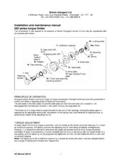
3 Operation General data 23 9. Troubleshooting General 24 Normal operation Troubleshooting guide 24-25 10. Maintenance and servicing General 26 Disassembly of sizes 1-5 26-27 Assembly of sizes 1 5 28-30 Disassembly of sizes 6 9 30-31 Assembly of Sizes 6 9 32-34 Lubricants 34 11. Spare parts & Service 34-35 Addresses of spare parts stockists and service facilities 35 Edition: 12/09 Page 3 of 35 1. Technical Data Standard parts (Figure 1) Part Number Description Spares Code Part Number Description Spares code 21 Hub B 42 Pawl B 22 Slide plate B 43 Tape journal bearing A 23 Adjusting nut C 44 Tape thrust bearing A 24 Strut ring C 45 Adapter ball bearing B 25 Drive plate B 46 Cage plate spring C 26 Cage plate B 52 Clamp collar C 27 Calibration spacer C 53 Adjustment spacer C 28 Adapter C 54 Adjuster screw C 29 Pawl spring A 55 Washer C 30 Torque spring outer (spring stack > size 5) C 56 Spring pillar C 31 Torque spring inner C 57 Ball bearing (SR strut ring only)
4 A 32 Drive balls A 58 Switch plate / cover B 33 Needle thrust bearing A 59 Switch plate fixing screw B 34 - 60 Felt strip switch plate cover A 35 Roll pin for SR pawl B 61 Drive plate cover B 36 Stop pin outer B 62 Felt strip drive plate cover A 37 Adapter bolt A 63 - 38 - 64 Locking peg C 39 Adapter dowel pin A 65 Locking peg screw C 40 Adjusting nut locking screw A 66 - 41 Stop pin inner B 67 Bearing spacer C Spares Codes: A = Standard service item spares stock is recommended B = Potential service item spares stock is recommended in critical applications C= Spares stock is not normally required For details of specifications, part number and quantities required for specific sizes and models, please contact Autogard or visit where full arrangement drawings and parts lists are available.
5 Edition: 12/09 Page 4 of 35 General Technical Data Size 1-5 Type RR (Rapid Reset) is supplied as standard. Type SR (Synchronous Reset) if supplied is specified with order. In the case of Type RR, Part 57 is omitted. In the case of type RR, parts 35 (anti-rotation pins from pawls) are omitted. Cage plate spring (46) is only used in Type SR Size 1 Protective cover (61) and sealing strips (60,62) are special equipment Figure 1 refers to a model 403. Refer to section for other models. RR Top SR Bottom Figure 1 Edition: 12/09 Page 5 of 35 Size Max Torque Setting Tmax Nm Speed (3) Nmax 1/min Dmax mm da mm d1 mm d2 mm x mm z mm k mm s lB mm l1 mm l3 mm l4 (1) mm Wt.
6 (2) kg 1 28 3000 16 62 30 110 5xM4 30 59 1 2 225 3000 28 112 75 140 92 6xM8 50 108 3 680 3000 40 146 95 184 114 7xM10 70 114 4 1130 2000 50 168 122 203 144 8xM12 75 121 15 5 2540 2000 75 222 155 280 184 8xM16 110 163 36 Table 1: Maximum actuating torque Tmax, speed nmax, weights and dimensions 1) Dimension without cover 61 2) Weights apply to maximum bore size 3) Higher speeds may be permitted consult Autogard.
7 The torque settings are applicable to: Daily operation up to 24 hours between operations. Operation in the temperature range from 30 C to +80 C (ambient temperature of shaft ends) Note that the set torque must be high enough to withstand start up torques. Autogard torque limiters are supplied with a durable surface protection, so that no painting is necessary. If however, paint is applied by the customer, the following points should be observed: - Do not clean the coupling by pressure washing or solvent dip. It may be wiped clean only. Grease and oil might be washed off which can only be replaced by disassembly of the torque limiter.
8 - The torque limiter may only be painted on its outer surfaces. When doing so, ensure that no paint is allowed to penetrate into the unit or into gaps between components. To ensure sustained trouble-free operation, the torque limiter must be designed for the application involved. In the event of any change in the operating conditions (Power, speed, modifications to prime mover and driven machine), it is essential to check the design. Caution ! Edition: 12/09 Page 6 of 35 Size 6-9 * In the case of type RR, parts 35 (anti-rotation pins for pawls) are omitted 403-RR Top 403-SR Bottom Edition: 12/09 Page 7 of 35 Size Max Torque Setting Tmax Nm Speed Nmax 1/min Dmax mm da mm D1 J6 Mm d2 mm w mm x mm z mm k mm s lB mm l1 mm l3 mm l4 mm Wt.
9 (1) kg 6 5650 1500 100 263 200 228 9x M16 150 217 24 79 55 7 8600 11300 1500 1500 125 480 520 265 295 6 440 480 10x M20 210 245 35 125 140 8 13800 17600 24850 1000 1000 1000 150 575 615 655 325 355 370 NA 8 528 568 608 10x M24 240 300 38 120 225 235 250 9 31600 40800 56500 1000 1000 950 175 730 780 830 410 440 480 NA 10 8 670 720 770 10x M30 270 410 40 158 530 550 570 Table 2: Maximum actuating torque Tmax, speeds nmax, weights and dimensions 1) Weights apply to maximum hole sizes The torque settings are applicable to: Daily operation up to 24 hours between operations.
10 Operating in the temperature range from 30 C to +80 C (ambient temp or temp of shaft ends.) Note that the set torque must be high enough to withstand start up torques. Autogard torque limiters are supplied with a durable surface protection, so that no painting is necessary. If however, paint is applied by the customer, the following points should be observed: - Do not clean the coupling by pressure washing or solvent dip. It may be wiped clean only. Grease and oil might be washed off which can only be replaced by disassembly of the torque limiter. - The torque limiter may only be painted on its outer surfaces.