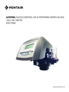
Transcription of Autotrol Performa™ ProSoft - swtwater.com
1 With 960 Series Control Water Conditioning Control SystemInstallation, Operation and Maintenance Manual Autotrol performa ProSoft 2 Table of ContentsInstallation .. 3 Location SelectionWater Line ConnectionDrain Line ConnectionBrine LineOverflow Line ConnectionPlacing Conditioner into Operation .. 5 Electrical Connection960 ProSoft Control .. 6 ProgrammingLevel I FeaturesLevel II FeaturesManual RegenerationAutomatic RegenerationRemoving the Valve Assembly for Servicing . 11 Preventive Maintenance .. 12 Injector Screen and InjectorWater MeterRemoving the Control.
2 13 Specifications .. 14 Pressure Graphs .. 15 Identification of Control Valving .. 16 Valve Disc Principle of Operation .. 16 Flow Diagrams .. 16 Replacement Parts .. 18 Troubleshooting .. 21 Disinfection of Water Conditioners .. 243 InstallationAll plumbing and electrical connections must conform to local unit carefully for carrier shortage or shipping Selection1. The distance between the unit and a drain should be as short as If it is likely that supplementary water treatment equipment will be required, make certain adequate additional space is Since salt must be added periodically to the brine tank, the location should be easily Do not install any unit closer to a water heater than a total run of 10 feet (3 m) of piping between the outlet of the conditioner and the inlet to the heater.
3 Water heaters can sometimes overheat to the extent they will transmit heat back along the cold pipe into the unit control water can severely damage the conditioner. A 10-foot (3-m) total pipe run, including bends, elbows, etc., is a reasonable distance to help prevent this possibility. A positive way to prevent hot water flowing from heat source to the conditioner, in the event of a reverse flow situation, is to install a check valve in the soft water piping from the conditioner. If a check valve is installed, make certain the water heating unit is equipped with a properly rated temperature and pressure safety relief valve.
4 Also, be certain that local codes are not Do not locate unit where it or its connections (including the drain and overflow lines) will ever be subjected to room temperatures under 34oF (1oC) or over 120oF (49oC).6. Do not install unit near acid or acid The use of resin cleaners in an unvented area is not Line ConnectionThe installation of a bypass valve system is recommended to provide for occasions when the water conditioner must be bypassed for hard water or for most common bypass systems are the Autotrol Series 1265 bypass valve (Figure 1) and plumbed-in globe valves (Figure 2).
5 Though both are similar in function, the Autotrol Series 1265 bypass offers simplicity and ease of 1 - Autotrol Series 1265 Bypass ValveFigure 2 - Typical Globe Valve Bypass SystemDrain Line ConnectionNote: Standard commercial practices are expressed here. Local codes may require changes to the following Ideally located, the unit will be above and not more than 20 feet ( m) from the drain. For such installations, using an appropriate adapter fitting, connect 1/2-inch ( ) plastic tubing to the drain line connection of the control If the backwash flow rate exceeds 5 gpm ( Lpm) or if the unit is located more than 20 feet ( m) from drain, use 3/4-inch ( ) tubing for runs up to 40 feet ( m).
6 Also, purchase appropriate fitting to connect the 3/4-inch tubing to the 3/4-inch NPT drain If the unit is located where the drain line must be elevated, you may elevate the line up to 6 feet ( m) providing the run does not exceed 15 feet ( m) and water pressure at conditioner is not less than 40 psi ( bar). You may elevate an additional 2 feet (61 cm) for each additional 10 psi ( bar) water in BypassIn BypassBYPASSBYPASSBYPASSBYPASSW aterConditionerInOutWaterConditionerInOu tWaterWaterNot in BypassIn BypassWaterConditionerWaterConditioner44 . Where the drain line is elevated but empties into a drain below the level of the control valve, form a 7-inch (18-cm) loop at the far end of the line so that the bottom of the loop is level with the drain line connection.
7 This will provide an adequate siphon Where the drain empties into an overhead sewer line, a sink-type trap must be : Never insert drain line into a drain, sewer line or trap. Always allow an air gap between the drain line and the wastewater to prevent the possibility of sewage being back-siphoned into the 3 Note: Standard commercial practices have been expressed here. Local codes may require changes to these Line ConnectionIt will be necessary to install the brine line to the brine fitting on the valve (3/8-inch NPT). Be sure all fittings and connections are Line ConnectionIn the absence of a safety overflow and in the event of a malfunction, the BRINE TANK OVERFLOW will direct overflow to the drain instead of spilling on the floor where it could cause considerable damage.
8 This fitting should be on the side of the cabinet or brine connect overflow, locate hole on side of brine tank. Insert overflow fitting (not supplied) into tank and tighten with plastic thumb nut and gasket as shown (Figure 4). Attach length of 1/2-inch ( ) tubing (not supplied) to fitting and run to drain. Do not elevate overflow line higher than 3 inches ( cm) below bottom of overflow fitting. Do not tie into drain line of control unit. Overflow line must be a direct, separate line from overflow fitting to drain, sewer or tub. Allow an air gap as per drain line instructions (Figure 3).
9 Figure 4 Battery Back-UpThe performa ProSoft conditioner features a battery back-up feature that will allow the controller to continue to keep time and record water usage during a power outage. The control s display will not light, but the controller will continue to measure water usage for up to five hours. When power is restored to the unit, it will continue to work as before. Connect a nine-volt alkaline battery to the connecting cable at the back of the conditioner s control box, Figure 5 Right WayBrine TankOverflow FittingInstalledConnect 1/2-inch ( )Tubing or Hose and Run to Drain5 Placing Conditioner into OperationAfter all previous steps have been completed, the unit is ready to be placed into operation.
10 Follow these steps Remove control valve cover by first depressing the plastic clips on the side of the cover. Pull front of cover : The following steps will require turning the cycle indicator (Figure 6) to various positions. Manually rotate the camshaft COUNTERCLOCKWISE only until cycle indicator points to desired position. (See manual regeneration sections for each control s manual operation.)2. Rotate cycle indicator COUNTERCLOCKWISE until it points directly to the word Fill media tank with With water supply off, place the bypass valve(s) into the service Open water supply valve very slowly to approximately the 1/4 open : If opened too rapidly or too far, media may be lost.
